Absorption-type unit concentrated solution bypass defrosting device

A concentrated solution and absorption technology, which is applied in the field of absorption unit concentrated solution bypass defrosting device, can solve the problems of complex process, low efficiency, large power consumption, etc., and achieve the effect of reducing energy loss, low cost and easy realization

Pending Publication Date: 2018-04-06
SHANDONG QIWEITE SOLAR TECH CO LTD
View PDF1 Cites 0 Cited by
  • Summary
  • Abstract
  • Description
  • Claims
  • Application Information

AI Technical Summary

Problems solved by technology

This kind of defrosting method consumes a lot of power, the electric control ...

Method used


Image

  • Absorption-type unit concentrated solution bypass defrosting device
  • Absorption-type unit concentrated solution bypass defrosting device

Examples


Embodiment 1

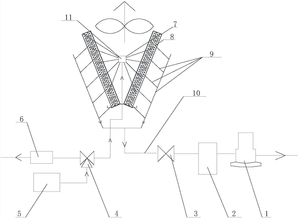
[0026] Example 1: See figure 1 , the present invention provides a concentrated solution bypass defrosting device for an absorption unit, comprising: a medium inflow pipeline and a medium outflow pipeline;

[0027] The medium inflow pipeline includes:

[0028] The absorber 5 is used to accommodate the concentrated solution medium;

[0029] The concentrated solution flow control device is an electromagnetic three-way valve 4, which is connected to the absorber 5, the casing 6 and the input end of the liquid separator 11 through pipelines;

[0030] Liquid separator 11, the output end of which is used to be connected to the evaporator of the heat pump unit; wherein, the evaporator includes an air-cooled finned heat exchanger 7, and the air-cooled finned heat exchanger 7 includes fins tube, the inner cavity of the finned tube is provided with a heat exchange coil and a defrosting coil 8, and the defrosting coil 8 is attached to the heat exchange coil; the output end of the liquid...

Embodiment 2

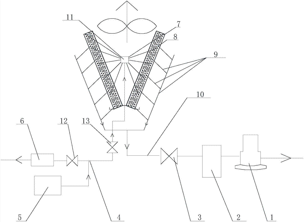
[0035] Example 2: See figure 1 The difference between embodiment 2 and embodiment 1 is that the concentrated solution flow control device includes a first control valve 12 and a second control valve 13, and the first control valve is arranged on the pipeline where the concentrated solution medium flows to the casing; The second control valve is arranged on the pipeline where the concentrated solution medium flows to the liquid separator.

[0036] When in use, when it is judged that the frosting condition is reached, close the electromagnetic three-way valve 4 (the first control valve 12 in embodiment 2) to enter the casing pipeline, and open the electromagnetic three-way valve 4 (the second control valve 12 in embodiment 2). Valve 13) into the valve of the liquid separation device 11, so that the high-temperature concentrated solution medium enters the outermost defrosting coil 8, and the defrosting coil 8 is close to the heat exchange coil of the air-cooled fin heat exchanger...


PUM


Abstract

The invention provides an absorption-type unit concentrated solution bypass defrosting device. The absorption-type unit concentrated solution bypass defrosting device comprises a medium flow-in pipeline and a medium flow-out pipeline. The medium flow-in pipeline comprises an absorber, a concentrated solution flowing direction control device and a liquid distributing device, wherein the absorber isused for containing a concentrated solution medium; the concentrated solution flowing direction control device is connected with the absorber, a casing pipe and the input end of the liquid distributing device through pipelines; and the output end of the liquid distributing device is used for being connected with an evaporator of a heat pump unit. The evaporator comprises an air-cooling finned heat exchanger. The air-cooling finned heat exchanger comprises a finned tube. A heat exchange coil pipe and a defrosting coil pipe are arranged in an inner cavity of the finned tube. The defrosting coilpipe is attached to the heat exchange coil pipe. The output end of the liquid distributing device is connected with the defrosting coil pipe through a pipeline. The medium flow-out pipeline comprisesa pump front filter and a solution pump. The input end of the pump front filter is connected with the defrosting coil pipe, and the output end of the pump front filter is connected with an inlet of the solution pump.

Description

technical field [0001] The invention relates to a defrosting device for a heat pump unit, in particular to a defrosting device for a concentrated solution bypass of an absorption type unit. Background technique [0002] At present, the defrosting of heat pumps has always been an important and difficult point of heat pump systems. When the air-cooled heat pump operates in an area prone to frost at an ambient temperature of -5°C~5°C, the water vapor in the air is easy to condense on the surface of the air-cooled fin heat exchanger, forming a frost layer. When the frost accumulates too much, it will affect the heat pump. The operation of the heat pump will reduce the working capacity of the heat pump, increase the operating cost, and even affect the life of the heat pump in serious cases. Therefore, certain methods must be used to remove the accumulated frost. As long as the heat pump is defrosting, it will consume time and energy, but frost must be defrosted. Therefore, how t...

Claims


Application Information

Patent Timeline
IPC IPC(8): F25B47/02F25B49/04
CPCF25B47/027F25B49/04F25B2347/02
Inventor 李文张凤学王凤波李群山姚洪李伟栋曹文超曹朋贤
Owner SHANDONG QIWEITE SOLAR TECH CO LTD
Why Eureka
Try Eureka