Tree lodging-resistant equipment for landscaping

A landscaping and anti-lodging technology, applied in the field of landscaping, can solve the problem that the anti-lodging device cannot be changed, and achieve the effect of preventing pests

Inactive Publication Date: 2018-04-10
广州华景建设有限公司
View PDF1 Cites 13 Cited by
  • Summary
  • Abstract
  • Description
  • Claims
  • Application Information

AI Technical Summary

Problems solved by technology

[0005] The invention proposes a tree anti-lodging device for landscaping, which solves the problem that the existing tree anti-lodging device cannot change with the growth of trees

Method used


Image

  • Tree lodging-resistant equipment for landscaping
  • Tree lodging-resistant equipment for landscaping
  • Tree lodging-resistant equipment for landscaping

Examples


Embodiment 1

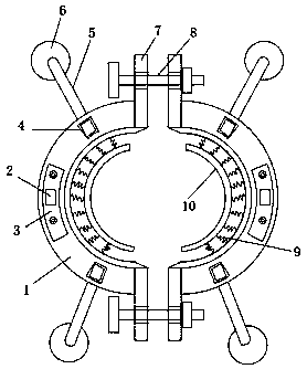
[0033] Embodiment one, with reference to Figure 1-6 , a tree lodging resistance device for landscaping, comprising two semicircular clamping seats 1 oppositely arranged, the two semicircular clamping seats 1 are pieced together to form a circular structure, the two semicircular clamping seats 1 Both ends are provided with mounting ears 7, bolts 8 are installed on the mounting ears 7 of the two semicircular clamp seats 1 close to each other, and multiple second springs 9 are fixed equidistantly on the arc-shaped inner wall of the semicircular clamp seats 1 One end of the second spring 9 is fixed with an arc-shaped splint 10. The present invention is equidistantly fixed with one end of a plurality of second springs 9 on the arc-shaped inner wall of the semicircular holder 1, and the other end of the second spring 9 One end is fixed with an arc-shaped splint 10, and two arc-shaped splints 10 form a ring structure. A buffer pad is bonded to the arc-shaped inner wall of the arc-sh...

Embodiment 2

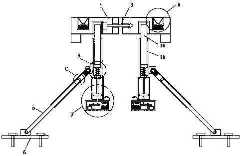
[0036] Embodiment two, refer to figure 2 and 5 , the outer side of the first hollow column 15 is hinged with a third hollow column 34, the hollow cavity of the third hollow column 34 is inserted with a solid column 5, and the end of the solid column 5 away from the third hollow column 34 is hinged on the fixed plate 6, Both sides of the solid column 5 positioned at the inside of the third hollow column 34 are provided with a spring groove 35, and one end of the third spring 36 is installed at the bottom of the spring groove 35, and the other end of the third spring 36 is fixed with a limit block 38, and the third hollow column 34 is provided with a limit groove 37 that matches the size and position of the limit block 38, and the limit block 38 is located in the limit groove 37. The present invention is provided with a limit block 38 through the third hollow column 34. The size and position of the matching limit groove 37, the limit block 38 is located in the limit groove 37,...

Embodiment 3

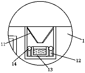
[0037] Embodiment three, refer to figure 2 and 6 , the lower end of the second hollow column 20 is fixed with an installation box 32, the lower end of the stay cord 22 extends into the installation box 32, the hanging ring 23 is located in the installation box 32, and the inner bottom side of the installation box 32 is fixed with a vertical rod 33, and The top of the vertical bar 33 is hinged on the side of the rotating rod 24, the vertical bar 33 and the bottom of the installation box 32 are vertically arranged, the control switch 25 is arranged on the inner bottom side of the installation box 32, and the inside of the installation box 32 is away from the side of the control switch 25 A control box 27 is installed, and an alarm 26 is installed on the top side of the installation box 32. The present invention is inserted into the inside of the first hollow column 15 through the lower end of the movable column 16, and is positioned at one end of the movable column 16 inside th...


PUM


Abstract

The invention belongs to the field of landscaping, in particular to a tree anti-lodging device for landscaping, aiming at the problem that the existing tree anti-lodging device cannot change with the growth of the tree, it includes two oppositely arranged semicircular clamping seats , two semi-circular clamps are pieced together to form a circular structure, both ends of the two semi-circular clamps are provided with mounting ears, and bolts are installed on the mounting ears of the two semi-circular clamps close to each other. The tops of the two semicircular holders are provided with installation grooves, and the middle position of the inner bottom of the installation groove is installed with a medicine storage box, and the medicine storage box is designed without a cover, and the inner bottom of the installation groove is provided with a plurality of support columns in the circumferential direction , the upper end of the support column is fixed with a lamp bead, the support column is arranged in the circumferential direction of the medicine storage box in a ring shape, a funnel-shaped cover is fixed on the top of the installation groove, and the top opening of the cover is larger than the bottom opening of the cover. The invention can change along with the growth of the trees, and is more intelligent, and the trees can grow more stably and healthily.

Description

technical field [0001] The invention relates to the technical field of landscaping, in particular to a tree lodging resistance device for landscaping. Background technique [0002] Using engineering technology and artistic means in a certain area, the beautiful natural environment and recreational environment created by transforming the terrain (or further building mountains, stacking stones, and water management), planting trees and flowers, building buildings, and arranging garden roads, etc. called gardens. Gardens include gardens, house gardens, small gardens, gardens, parks, botanical gardens, zoos, etc. With the development of gardening disciplines, they also include forest parks, scenic spots, nature reserves or tourist areas of national parks, and resorts. [0003] Patent No. CN201420682849.7 proposes a tree anti-lodging fixing device, which includes a fixing assembly and a fixing rod. The fixing assembly includes fastening bolts and two fixing seats arranged symmet...

Claims


Application Information

Patent Timeline
Patent Type & Authority Applications(China)
IPC IPC(8): A01G17/14A01M1/04A01M1/20
CPCA01G17/14A01M1/04A01M1/20
Inventor 潘杰良王宋双
Owner 广州华景建设有限公司
Why Eureka
Try Eureka