
Drilling positioning device for steel plate

A technology of positioning device and steel plate, applied in the direction of positioning device, boring/drilling, drilling/drilling equipment, etc., can solve the problem that the adjustment accuracy of the fixture position is difficult to guarantee, it is difficult to judge whether the position of the steel plate is accurate, and the position deviation of the fixture can be solved. and other problems, to achieve the effect of convenient replacement of ruler, flexible use and accurate processing position

Inactive Publication Date: 2018-04-10
天津曹氏传动机械制造有限公司
View PDF0 Cites 1 Cited by
  • Summary
  • Abstract
  • Description
  • Claims
  • Application Information

AI Technical Summary

Problems solved by technology

[0002] When the steel plate is drilled, the steel plate needs to be positioned. The existing positioning device usually uses a clamp to fix the steel plate under the drilling device. The position of the clamp is usually preset, and it is difficult to judge during the drilling process. Whether the position of the steel plate is accurate and whether there is any deviation in the position of the fixture
As a result, the hole position is inaccurate during processing, and when processing steel plates of different sizes, the accuracy of fixture position adjustment is difficult to guarantee

Method used


Image

  • Drilling positioning device for steel plate
  • Drilling positioning device for steel plate
  • Drilling positioning device for steel plate

Examples


Embodiment Construction

[0015] Below, the substantive features and advantages of the present invention will be further described in conjunction with examples, but the present invention is not limited to the listed examples.

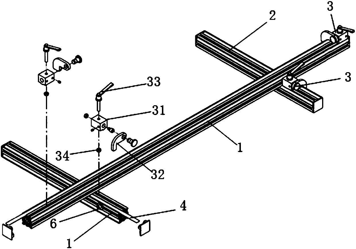
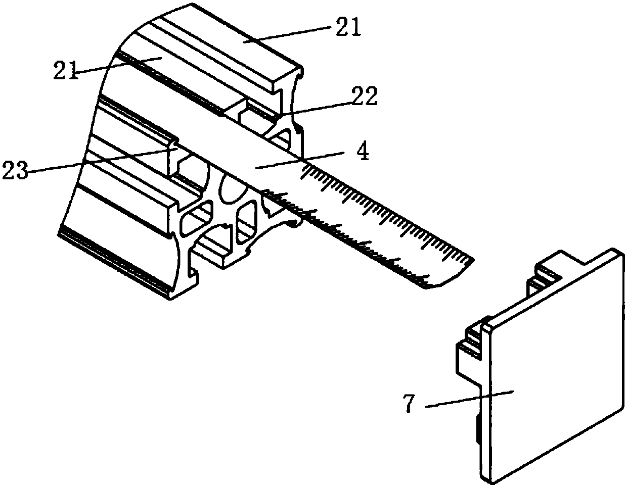
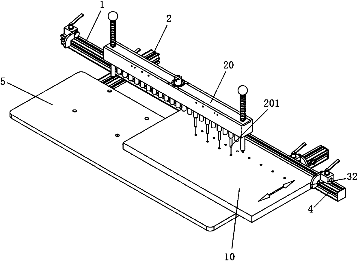
[0016] Such as Figure 1 to Figure 3 As shown, a steel plate drilling positioning device in this embodiment includes a first track 1, a second track 2, a sliding device 3, a ruler bar 4 and a support plate 5, the second track 2 is arranged at intervals, and the first track 1 spans Above the second track 2. The support plate 5 is arranged on the second track 2, and the sliding device 3 is arranged on the first track and the second track, and the first track and the second track are tracks with the same structure. The track includes a sliding surface 21, a sliding groove 22 and a mounting groove 23, the sliding groove 22 and the mounting groove 23 are arranged at intervals, and the sliding surface 21 is arranged on the surface of the track and located on both sides of the sliding...


PUM


Abstract

The invention relates to a steel plate drilling positioning device, comprising a first track, a second track, a sliding device, a ruler bar and a support plate, the second track is arranged at intervals, the first track is straddled above the second track, and the support plate is set on the On the second track, the sliding device is arranged on the first track and the second track, the first track and the second track are tracks with the same structure, and the track includes a sliding surface, a sliding groove and a mounting groove, and the distance between the sliding groove and the mounting groove is Setting, the sliding surface is set on the surface of the track and located on both sides of the sliding groove, the sliding device includes a sliding seat, a baffle, a fixed rod and a nut, the sliding seat is set on the sliding surface, the baffle is set on the side of the sliding seat, and the nut is set on In the slide groove, the fixed rod passes through the slide seat and is threadedly connected with the nut, the ruler bar is inserted in the installation groove, and the baffle plate is arranged above the installation groove. The invention can directly adjust and locate the position of the steel plate according to the value of the ruler bar, so that the processing position of the steel plate is more accurate.

Description

technical field [0001] The invention relates to a positioning device, in particular to a steel plate drilling positioning device. Background technique [0002] When the steel plate is drilled, the steel plate needs to be positioned. The existing positioning device usually uses a clamp to fix the steel plate under the drilling device. The position of the clamp is usually preset, and it is difficult to judge during the drilling process. Whether the position of the steel plate is accurate and whether there is any deviation in the position of the fixture. As a result, the hole position is inaccurate during processing, and when processing steel plates of different sizes, it is difficult to ensure the accuracy of fixture position adjustment. Contents of the invention [0003] In order to solve the problems of the prior art, the present invention provides a steel plate drilling positioning device with higher positioning accuracy, more intuitive position display and convenient an...

Claims


Application Information

Patent Timeline
IPC IPC(8): B23Q3/18B23B41/00
CPCB23Q3/18B23B41/00
Inventor 曹云明
Owner 天津曹氏传动机械制造有限公司
Learn More