Laser engraving thermal fusion forming 3D printing method and 3D printing equipment

A 3D printing, laser engraving technology, applied in metal processing equipment, 3D object support structure, additive manufacturing, etc., can solve problems such as slow printing speed

Active Publication Date: 2021-07-02
ZHEJIANG IND & TRADE VACATIONAL COLLEGE
View PDF2 Cites 1 Cited by
  • Summary
  • Abstract
  • Description
  • Claims
  • Application Information

AI Technical Summary

Problems solved by technology

However, the above technologies all need to fuse and shape the print

Method used


Image

  • Laser engraving thermal fusion forming 3D printing method and 3D printing equipment
  • Laser engraving thermal fusion forming 3D printing method and 3D printing equipment
  • Laser engraving thermal fusion forming 3D printing method and 3D printing equipment

Examples


Embodiment Construction

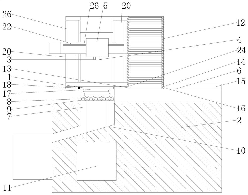
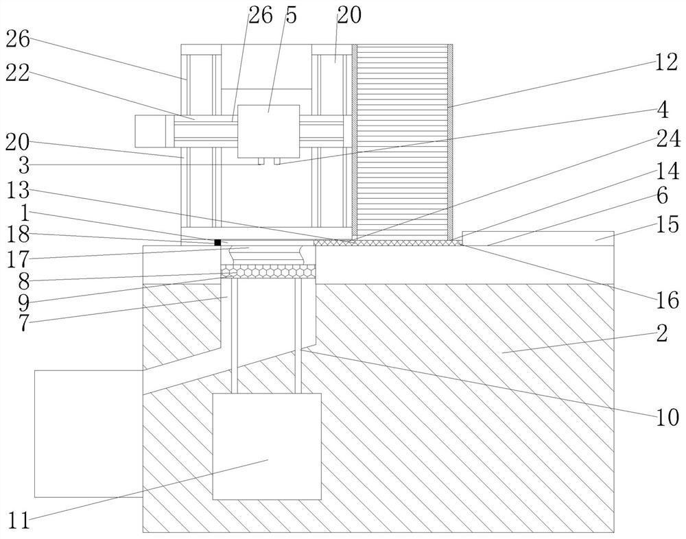
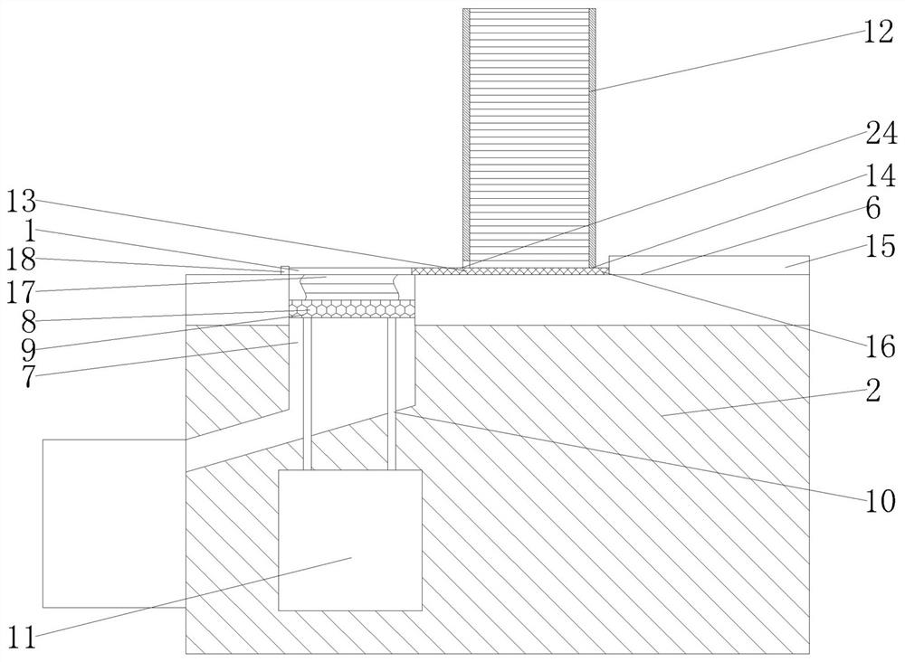
[0021] The present invention will be described in further detail below in conjunction with the accompanying drawings and embodiments. Wherein the same components are denoted by the same reference numerals. It should be noted that the words "front", "rear", "left", "right", "upper" and "lower" used in the following description refer to the directions in the drawings, and the words "bottom" and "top "Face", "inner" and "outer" refer to directions toward or away from, respectively, the geometric center of a particular component.

[0022] refer to Figure 1-6 As shown, the laser engraving thermal fusion molding 3D printing method provided by the present invention includes:

[0023] Step 1: Use a computer to model the 3D object to be printed, and the computer processor analyzes the pattern and shape of each unit thickness layer based on the three-dimensional data model of the 3D object;

[0024] Step 2: Using a laser engraving and cutting mechanism to emit laser to cut and engra...


PUM


Abstract

The invention discloses a laser engraving thermal fusion forming 3D printing method. The method comprises the steps that firstly, a computer is adopted for modeling a 3D article to be printed, and a computer processor analyzes the pattern and shape of each unit thickness layer based on a three-dimensional data model of the 3D article; 2, a laser engraving and cutting mechanism is adopted for emitting laser to cut and engrave blank pieces according to the pattern and shape of a unit layer, the thickness of the blank pieces is the same as the unit thickness, the blank pieces are stacked layer by layer, and the 3D article is formed through heating or laser irradiation bonding; and 3, the formed 3D article is modified in a mode of grinding or laser engraving. The invention further relates to 3D printing equipment used in the laser engraving thermal fusion forming 3D printing method. According to the method and equipment, the blank pieces are adopted for machining, rapid forming can be achieved, and the speed is higher.

Description

technical field [0001] The invention relates to a 3D printing method of laser engraving thermal fusion molding. The present invention also relates to a 3D printing device used in the above laser engraving thermal fusion molding 3D printing method. Background technique [0002] 3D printing is a kind of rapid prototyping technology. It is a technology based on digital model files and using bondable materials such as powdered metal or plastic to construct objects by layer-by-layer printing. In 3D printing, a filamentous material such as thermoplastic, wax or metal is usually extruded from a heated nozzle, and the melt is deposited at a fixed rate according to the predetermined trajectory of each layer of the part. However, the above-mentioned technologies all need to fuse and shape the printing material layer by layer, so the printing speed is relatively slow. Contents of the invention [0003] The technical problem to be solved by the present invention is to provide a lase...

Claims


Application Information

Patent Timeline
IPC IPC(8): B29C64/147B29C64/20B29C64/379B29C64/393B22F3/105B22F10/85B22F10/60B22F10/66B33Y10/00B33Y30/00B33Y40/20B33Y50/02
CPCB29C64/147B29C64/20B29C64/379B29C64/393B22F3/24B33Y10/00B33Y30/00B33Y40/20B33Y50/02B22F2003/247Y02P10/25
Inventor 关雷郑道友徐临超
Owner ZHEJIANG IND & TRADE VACATIONAL COLLEGE
Why Eureka
Try Eureka