Transmission Mechanism and Tilt Rotor UAV

A transmission mechanism and transmission gear technology, applied in the field of drones, can solve problems such as easy bending and damage of lines, large gyro effect, safety accidents, etc., and achieve the effect of reducing impact, small gyro effect, and avoiding line failure

Active Publication Date: 2019-12-13
GOERTEK ROBTICS CO LTD
View PDF6 Cites 0 Cited by
  • Summary
  • Abstract
  • Description
  • Claims
  • Application Information

AI Technical Summary

Problems solved by technology

[0003] The tilting part of the existing tilting-rotor drone is a drive motor, a transmission mechanism and a rotor, and the tilting of the rotor is realized by turning the entire tilting part, so that the tilting part is connected with the main body of the tilting-rotor drone Parts are prone to wear and tear, especially the lines connected to the drive motor are easily bent and damaged
In addition, due to the large mass of the tilting part, the gyroscopic effect on the tilting part is relatively large when the rotor rotates, which is prone to safety accidents

Method used


Image

  • Transmission Mechanism and Tilt Rotor UAV
  • Transmission Mechanism and Tilt Rotor UAV
  • Transmission Mechanism and Tilt Rotor UAV

Examples


Embodiment 1

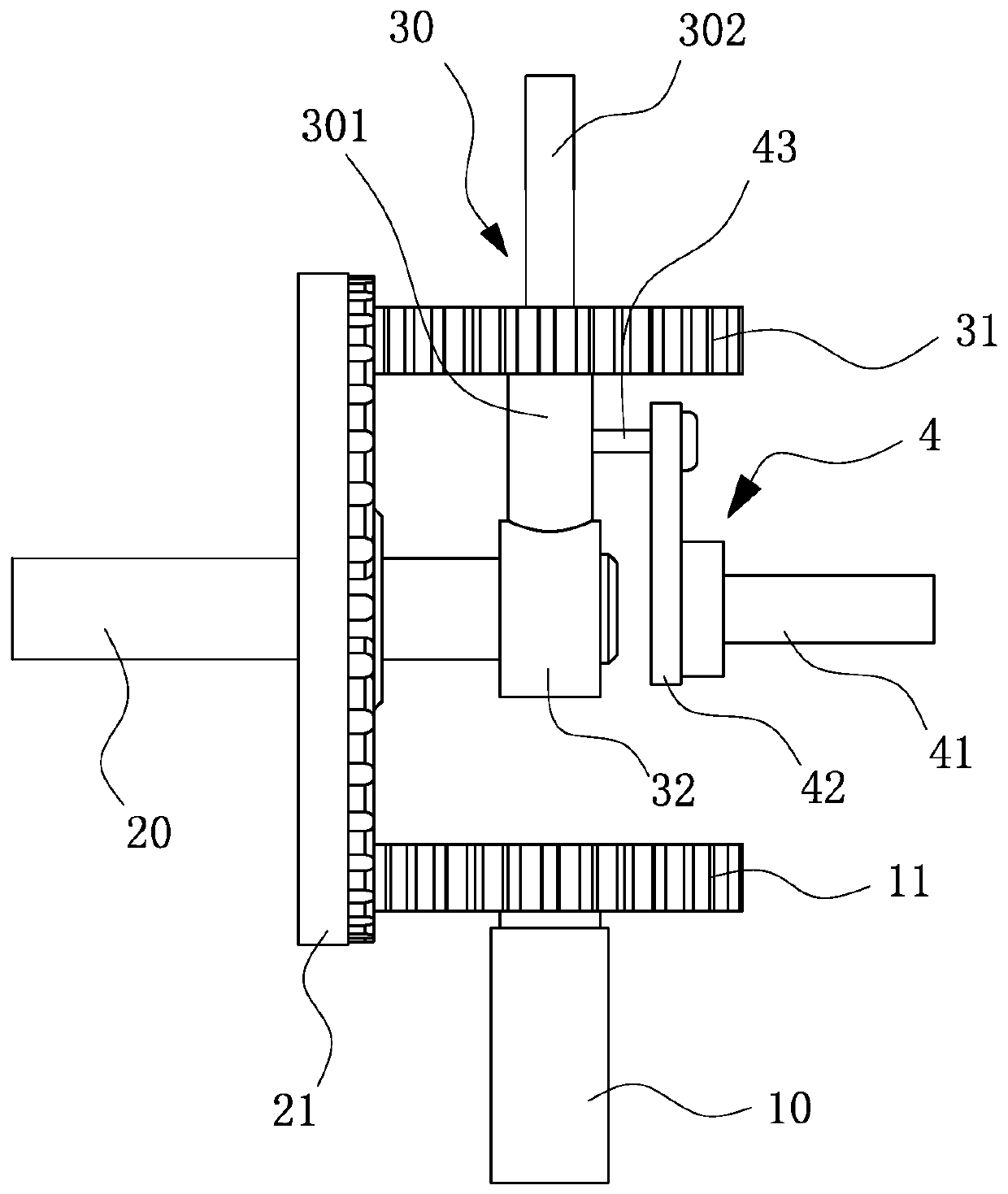
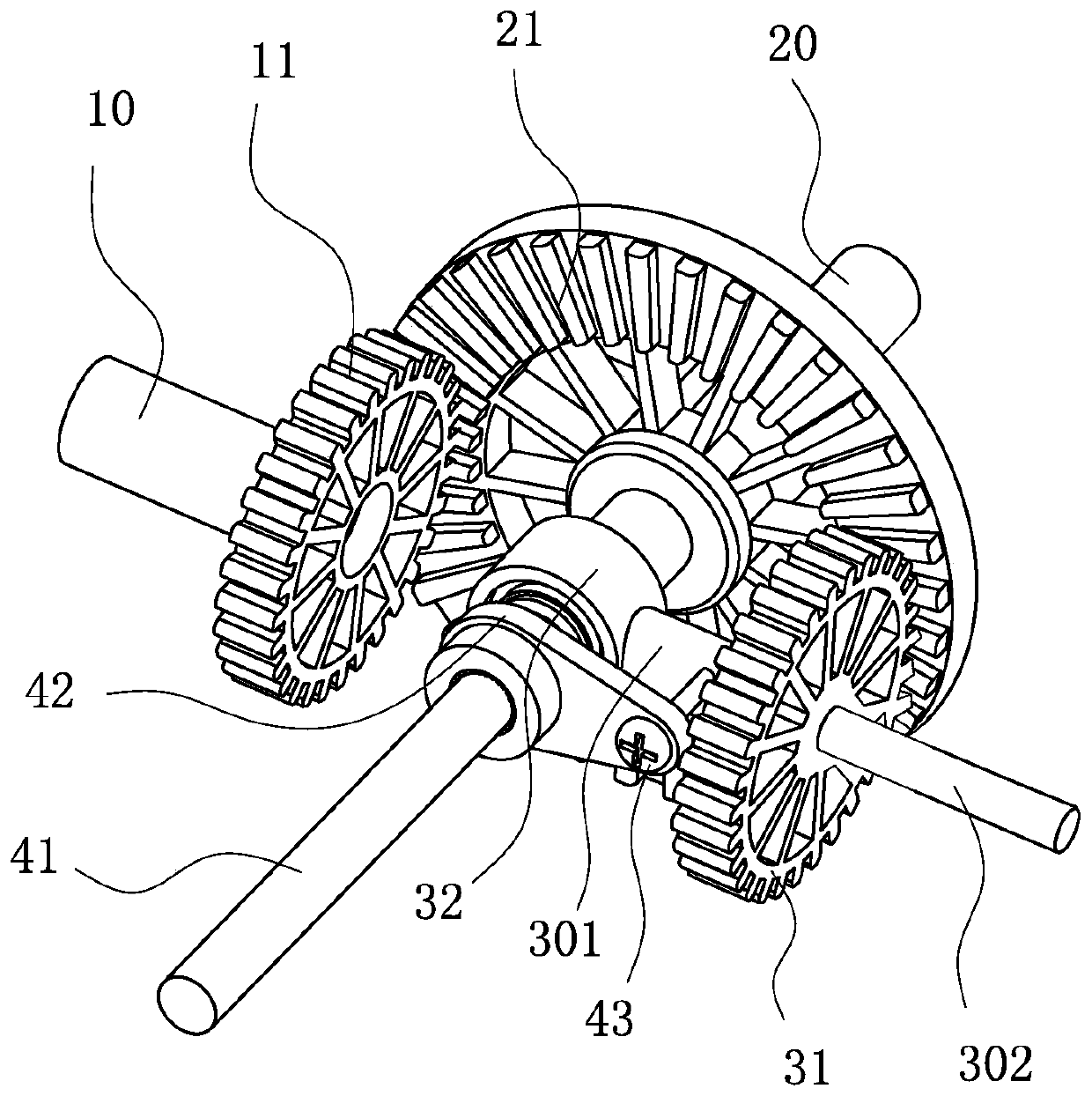
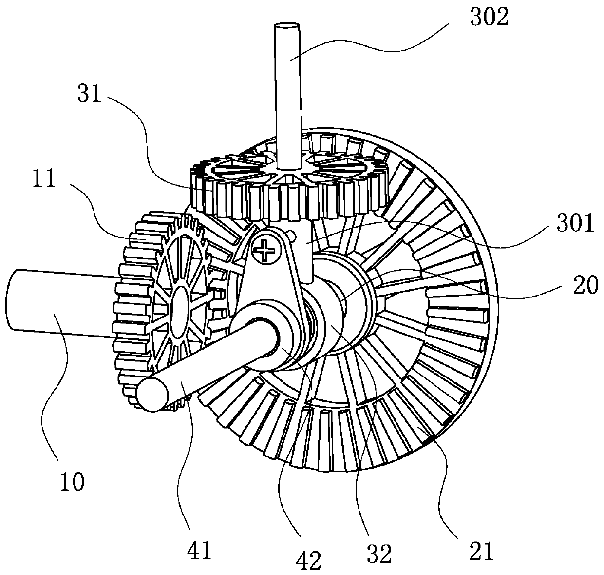
[0030] like figure 1 , figure 2 as well as image 3 Commonly shown, a transmission mechanism includes a first shaft 10 and a second shaft 20 arranged vertically at intervals. The first shaft 10 and the second shaft 20 may be in a vertical relationship in the same plane, but they may not touch each other, or It is the spatial vertical relationship of different planes. The driving gear 11 is coaxially installed on the first shaft 10, and the transmission gear 21 meshing with the driving gear 11 is coaxially installed on the second shaft 20. The transmission mechanism also includes The third shaft 30 arranged radially of 20, that is, the third shaft and the second shaft are located in the same plane and are perpendicular to each other. The third shaft 30 is controlled by the control assembly 4 to rotate around the second shaft 20. On the third shaft 30, the same The shaft is equipped with a driven gear 31 meshed with the transmission gear 21. The first shaft 10 is connected to...

Embodiment 2

[0036] A tilt-rotor unmanned aerial vehicle, comprising a motor 5 and a rotor 6 connected through the transmission mechanism, the first shaft 10 of the transmission mechanism is coaxially connected with the motor 5, and the third shaft 30 of the transmission mechanism is the same as the hub of the rotor 6 Shaft connection, when the rotor 6 of the tilt-rotor UAV rotates horizontally, the vertical take-off and landing of the tilt-rotor UAV can be realized, and when the rotor 6 rotates vertically, the high-speed and efficient cruise of the tilt-rotor UAV can be realized. 6 is connected with the motor 5 through a tiltable transmission mechanism, and the third shaft 30 of the tiltable transmission mechanism rotates around the second shaft 20 to realize the back and forth adjustment of the rotor 6 between horizontal plane rotation and vertical plane rotation, and During the tilting process of the rotor 6, it is always rotating, which realizes the tilting of the rotor 6 without the mo...


PUM


Abstract

The invention discloses a transmission mechanism and relates to the technical field of unmanned aerial vehicles. The transmission mechanism comprises a first shaft and a second shaft, wherein the first shaft is perpendicular to the second shaft in a spaced mode. A driving gear is coaxially and fixedly connected with the first shaft, a transmission gear meshing with the driving gear is coaxially installed on the second shaft, and the transmission mechanism further comprises a third shaft which is arranged in the radial direction of the second shaft. The third shaft is controlled by a control assembly to rotate around the second shaft, and a driven gear meshing with the transmission gear is coaxially installed on the third shaft. By means of the transmission mechanism, the technical problemthat a transmission mechanism in the prior art cannot be partly tilted is solved, the transmission mechanism can quickly tilt under the condition of maintaining norm transmission, and the transmissionmechanism is simple and compact in structure, high in safety and wide in application range, and is little affected by gyroscopic effects.

Description

technical field [0001] The invention relates to the technical field of unmanned aerial vehicles, in particular to a tiltable transmission mechanism and a tilting rotor unmanned aerial vehicle provided with the transmission mechanism. Background technique [0002] Among UAVs, rotary-wing UAVs can take off and land vertically, but their flight speed is not as good as that of fixed-wing aircraft, and their long-distance flight capabilities are poor. Although fixed-wing UAVs have strong long-distance flight capabilities and fast flight speeds, it takes a long time Based on the advantages and disadvantages of the two, people have produced tilt-rotor UAVs. The rotor orientation of the tilt-rotor UAVs can be tilted, so as to realize the difference between the rotor UAVs and the fixed-wing UAVs. convert. [0003] The tilting part of the existing tilting-rotor drone is a drive motor, a transmission mechanism and a rotor, and the tilting of the rotor is realized by turning the whole ...

Claims


Application Information

Patent Timeline
Patent Type & Authority Patents(China)
IPC IPC(8): B64C27/59
CPCB64C27/59
Inventor 韩伟李洪臣颜安石翔
Owner GOERTEK ROBTICS CO LTD
Why Eureka
Try Eureka