
Objective lens drive device and optical head device

一种驱动装置、物镜的技术,应用在光学记录头、头的配置/安装、用光学方法记录/重现等方向,能够解决物镜控制困难等问题,达到提高刚性的效果

Inactive Publication Date: 2007-05-30
SANKYO SEIKI MFG CO LTD
View PDF4 Cites 0 Cited by
  • Summary
  • Abstract
  • Description
  • Claims
  • Application Information

AI Technical Summary

Problems solved by technology

Therefore, it is difficult to control the objective lens toward the focusing direction, the tracking direction, or the tilting direction at high speed while reducing the value of the high-order resonance frequency.

Method used


Image

  • Objective lens drive device and optical head device
  • Objective lens drive device and optical head device
  • Objective lens drive device and optical head device

Examples


Embodiment Construction

[0026] The best mode for carrying out the present invention will be described below with reference to the accompanying drawings.

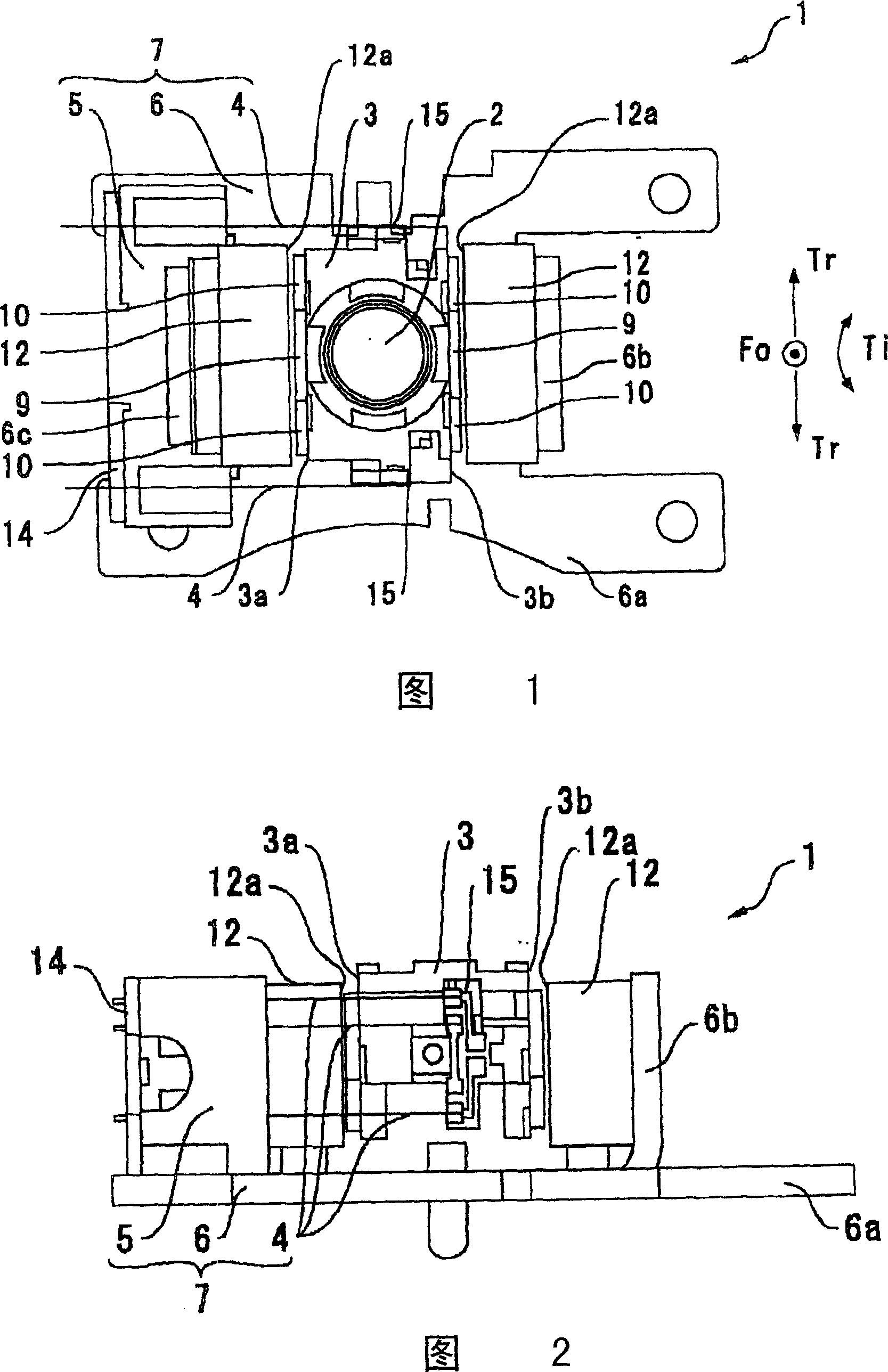
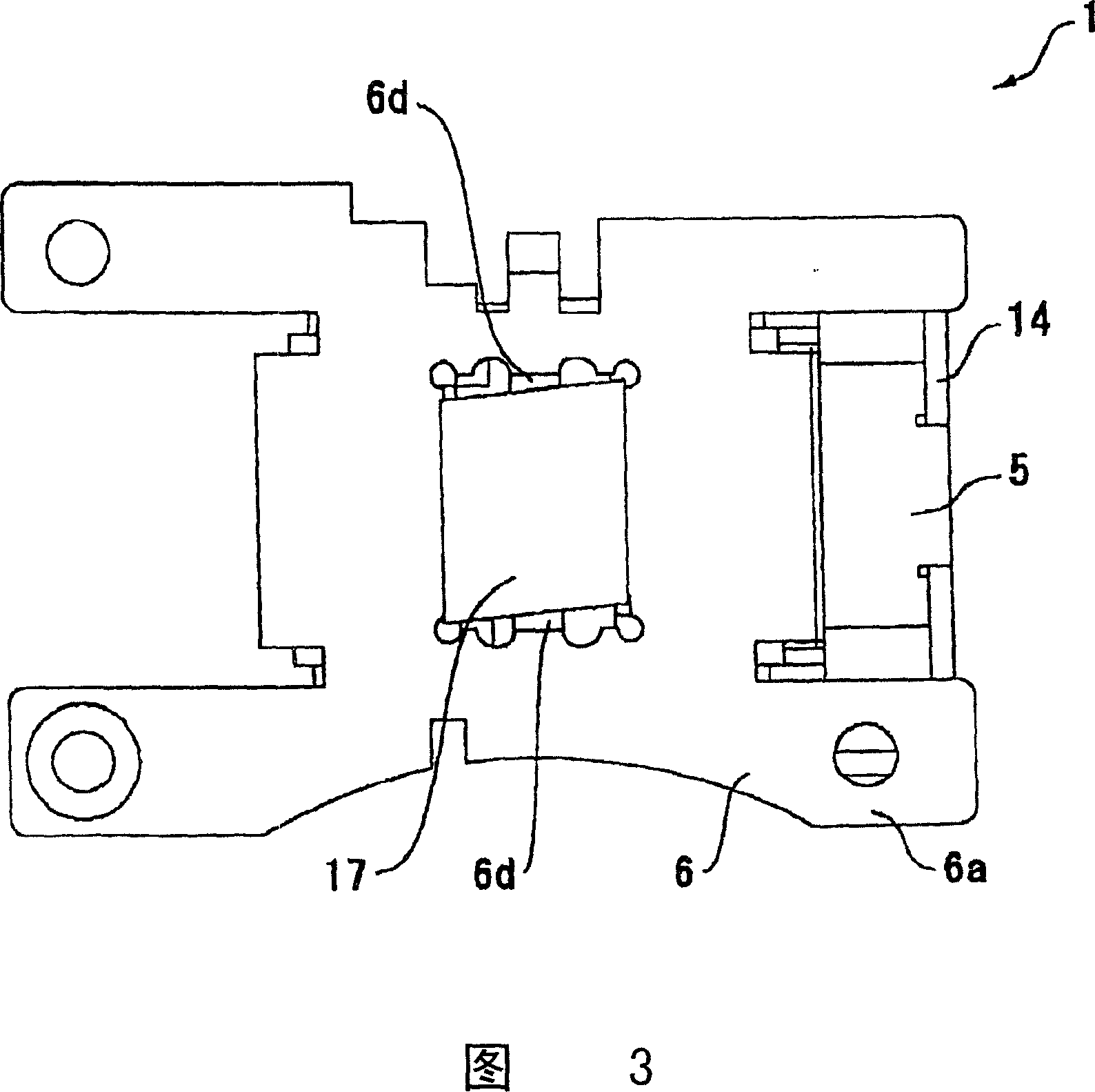
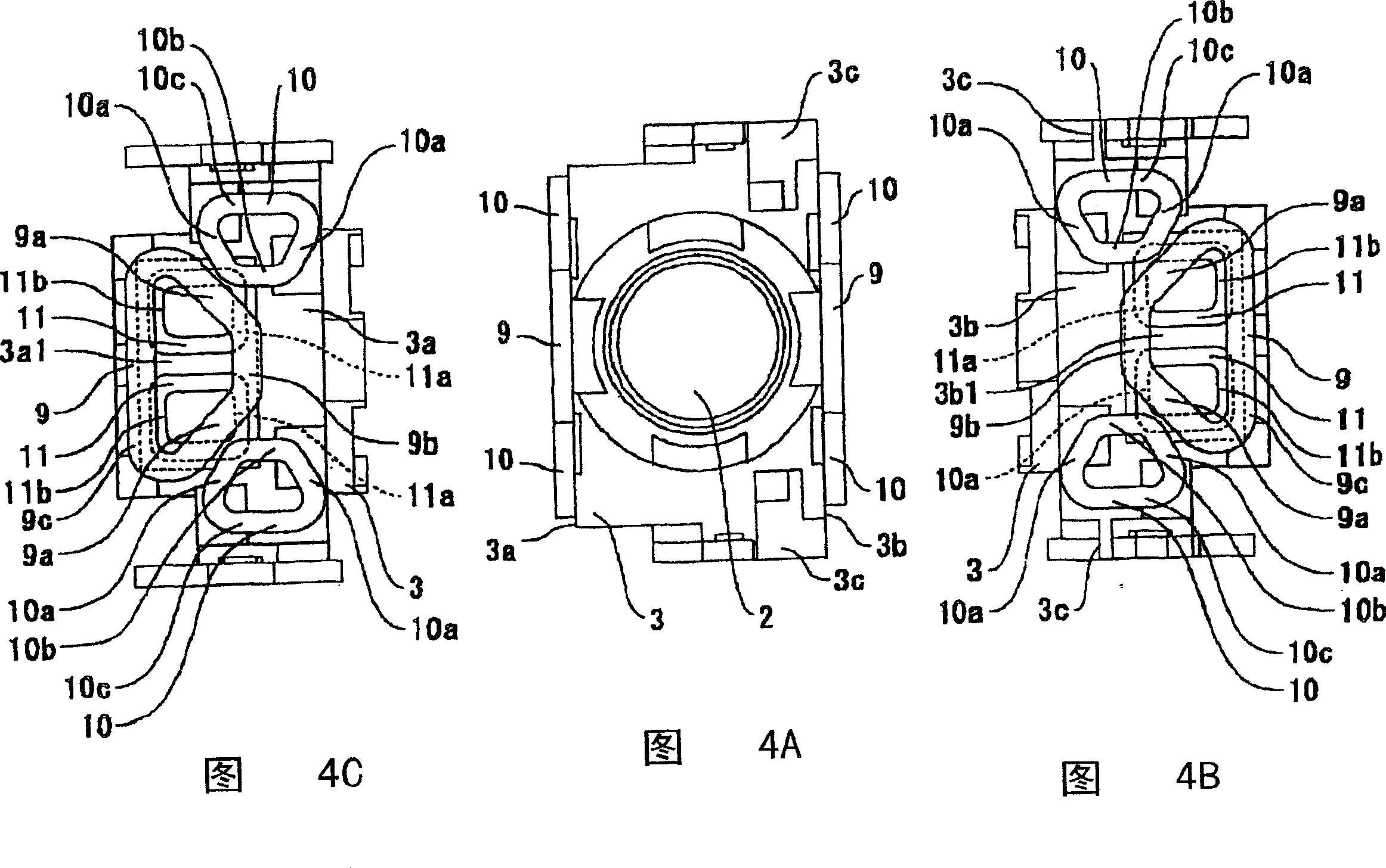
[0027] FIG. 1 is a plan view showing an objective lens driving device in an embodiment of the present invention. Fig. 2 is a side view of the objective lens driving device shown in Fig. 1 . Fig. 3 is a bottom view of the objective lens driving device shown in Fig. 1 . Fig. 4 shows the lens holder with the objective lens and each driving coil installed, (A) is a plan view of the lens holder, (B) and (C) are explanatory diagrams when the lens holder is viewed from the side of the proximal side and the lens is viewed from the side of the front end Explanatory diagram of the stand.

[0028] (Schematic structure of the objective lens drive unit)

[0029] In FIGS. 1 to 4, the objective lens driving device 1 of this embodiment has a predetermined optical system and is used in an optical head device for recording and reproducing information on an optica...


PUM


Abstract

The invnetion provides a configuration capable of responding to high speed while having a tilt function, in an objective lens driving device using a driving magnet with a magnetized counter face to which a different magnetic pole adjoins via an almost U-shaped magnetic pole boundary part. The objective lens driving device 1 is provided with a driving magnet 12 having a magnetized counter face 12a by polarized and magnetized by an almost U-shaped magnetic pole parting line 12b, and a focus drive coil 9 and a tracking drive coil 10 which are faced to the magnetized counter face 12a as straddling the magnetic pole parting line 12b. Moreover, in the direction in which the focus drive coil 9 and tracking drive coil 10 are opposed to the magnetized counter face 12a, the objective lens driving device 1 has a tilt drive coil 11 located to be faced to the magnetized counter face 12a so as to be superposed on the focus drive coil 9 and the tracking drive coil 10.

Description

technical field [0001] The present invention relates to a so-called wire suspension type objective lens driving device and an optical head device having the same. Background technique [0002] As an optical head device used in recording, reproducing, etc. of an optical recording disc such as a CD or DVD, an optical head device having a so-called wire suspension type objective lens driving device is used. The objective lens driving device has an objective lens and a lens for holding the objective lens. A bracket, a fixed side member capable of moving the lens bracket and supported by a plurality of metal wires, and a driving mechanism for driving the lens bracket at least in a focusing direction and a tracking direction. [0003] As the objective lens driving device used in this optical head device, there is known a kind of objective lens driving device driven by two shafts. A U-shaped magnetic pole boundary portion has a pair of drive magnets arranged to have magnetized opp...

Claims


Application Information

Patent Timeline
Patent Type & Authority Patents(China)
IPC IPC(8): G11B7/09G11B7/12G11B7/095G11B7/00
CPCG11B7/0933G11B7/0935
Inventor 坂本学横内毅
Owner SANKYO SEIKI MFG CO LTD
Learn More