

Electromagnetic catapult with tilting function and based on wireless power transmission
A technology of wireless power transmission and tilting function, which is applied in the direction of launch/drag transmission, etc., and can solve the problems of no tilting function and high equipment power requirements
Inactive Publication Date: 2018-01-16
HUBEI SIZE NEW ENERGY TECH CO LTD
View PDF6 Cites 2 Cited by
- Summary
- Abstract
- Description
- Claims
- Application Information
AI Technical Summary
Problems solved by technology
[0002] At present, the electromagnetic ejection devices for carrier-based aircraft that have been applied for or authorized are all set horizontally and have no tilt function. If you want to eject large-tonnage carrier-based aircraft such as fighter jets, you need greater ejection force and faster take-off speed. High requirements on equipment power
Method used
View moreImage
Smart ImageViewing Examples

Examples
Embodiment Construction
[0011] Summary of the Invention The specific implementation of the present invention has been described in detail, and will not be repeated here. It needs to be explained: the linear motor of the present invention adopts a tubular linear motor with a long stator and a short mover. The working principle of this linear motor is a known technology. , will not be repeated here, certainly the linear motor of the present invention needs necessary control equipment; If the carrier-based aircraft of small tonnage such as ejection fighter is to be launched, the movable ejector is in a horizontal state.
Login to View More PUM
 Abstract
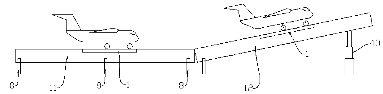
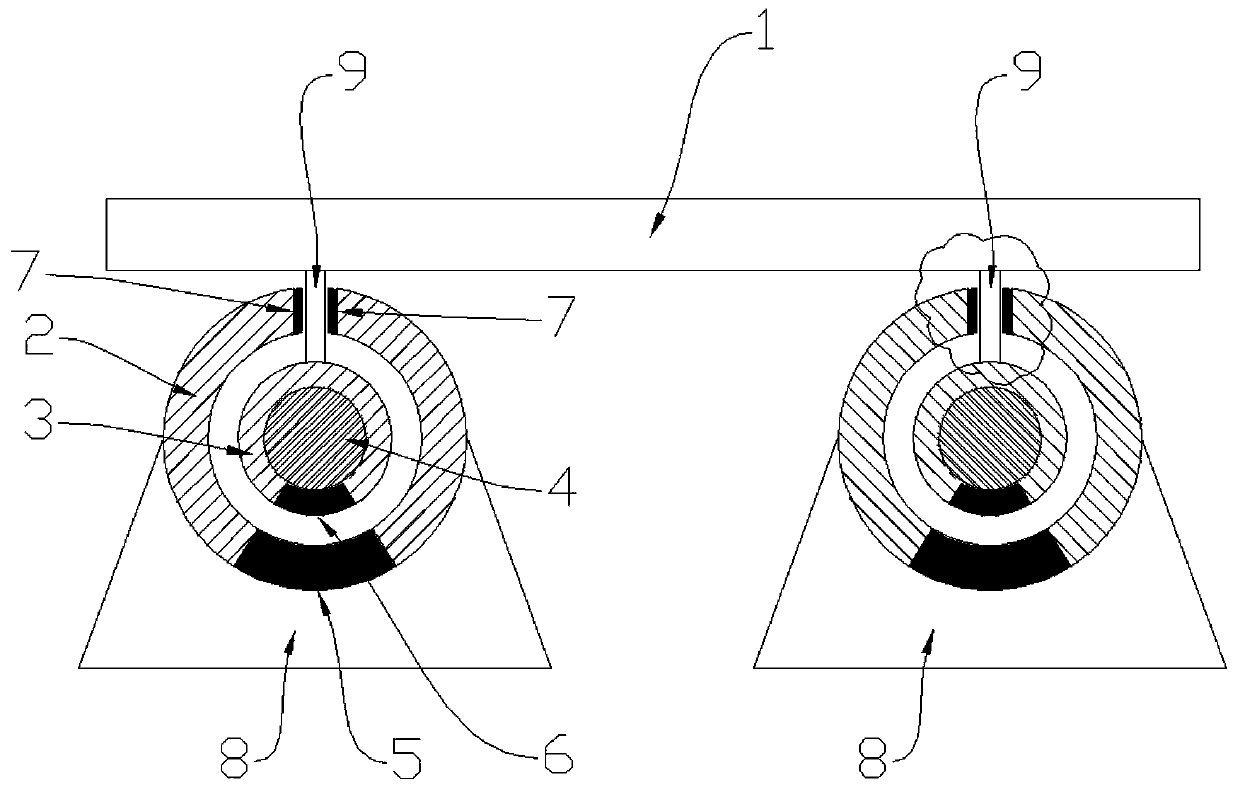
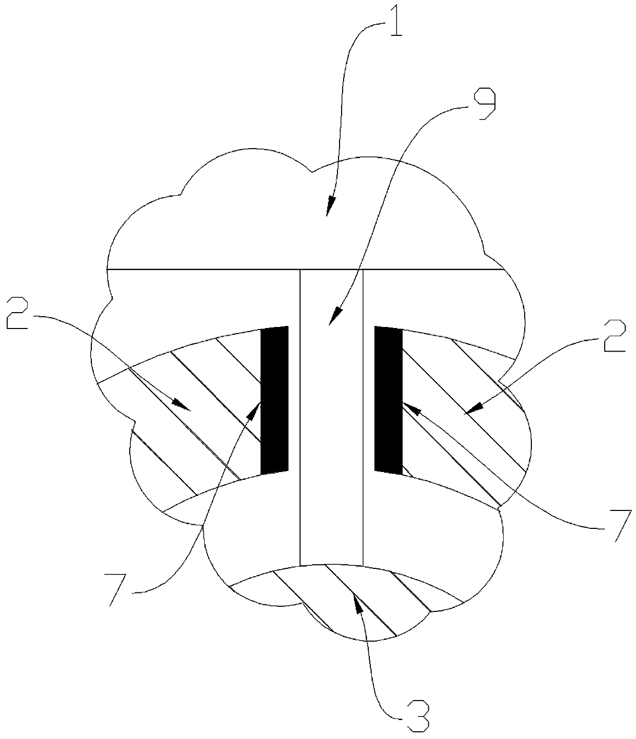
An electromagnetic catapult with a tilting function and based on wireless power transmission provided by the invention is mainly used for launching of a carrier-based aircraft on an aircraft carrier.The electromagnetic catapult consists of a platform, a static catapult and a movable catapult. The electromagnetic catapult works by parking and gripping the carrier-based aircraft on the platform while the platform is positioned at the left end of the static catapult, starting suspension electromagnets A to suspend the platform, then starting two linear motor rotors which can drive the platform to accelerate to move forward on the static catapult, jacking the right end of the movable catapult by a jacking hydraulic system to enable the platform to uptilt at an angle so that the carrier-basedaircraft can take off after the platform moves to the left end of the movable catapult, and starting reverse power sources of the two linear motor rotors so that the linear motor rotors can move backwards along linear motor stators and drive the platform to move backwards to be reset after the carrier-based aircraft takes off. Throughout the launching process, primary coils of the linear motor stators transmit electrical energy to the linear motor rotors by virtue of the wireless power transmission technique.
Description
technical field [0001] The invention is mainly used for taking off of aircraft carriers. Background technique [0002] At present, the electromagnetic ejection devices for carrier-based aircraft that have been applied for or authorized are all set horizontally and have no tilt function. If you want to eject large-tonnage carrier-based aircraft such as fighter jets, you need greater ejection force and faster take-off speed. High requirements on equipment power. Contents of the invention [0003] The present invention solves the above problems. It has a tilting function and requires low equipment power; it consists of a platform (1), a stationary catapult (11), and a movable catapult (12); the stationary catapult (11) mainly includes two A symmetrically arranged linear motor stator (2) and corresponding linear motor mover (3), central shaft (4), base (8), connecting plate (9); the movable ejector (12) mainly includes two symmetrical Arranged linear motor stator and corresp...
Claims
Login to View More Application Information
Patent Timeline
 IPC IPC(8): B64F1/06
Inventor彭宝安
OwnerHUBEI SIZE NEW ENERGY TECH CO LTD