
Rifle internally-installed positioning lock

A technology for positioning locks and guns, which is applied to weapon accessories, breech mechanism, offensive equipment, etc. It can solve the problems of difficult gun management, easy damage, harmful social impact, etc., and achieves the effect of easy disassembly and simple installation

Pending Publication Date: 2018-04-10
南京佳普科技有限公司
View PDF7 Cites 0 Cited by
  • Summary
  • Abstract
  • Description
  • Claims
  • Application Information

AI Technical Summary

Problems solved by technology

However, the management of guns on duty has always been a difficult point. Incidents of guns being robbed and sentries on duty leaving with guns have occurred from time to time, causing social harm and great social impact
[0003] The current gun locators on the market are mainly used to install anti-tamper locators on the outside of the gun or place the locator in the accessory clip. The main disadvantages are as follows: First, the locator is bound outside the gun, which affects the use and performance of the gun. At the same time, it also affects the appearance of the gun. Second, although the locator is bound on the outside of the gun, although it is anti-dismantlement, it is easy to be damaged after long-term use, which affects the performance of the locator. Third, it is inconvenient to manage and replace the bound locator. It is very inconvenient to replace the battery or charge. Fourth, the locator installed in the accessory clip cannot be locked. Performance and beautiful positioning locks are of great significance to improve the management of guns in the army

Method used


Image

  • Rifle internally-installed positioning lock
  • Rifle internally-installed positioning lock
  • Rifle internally-installed positioning lock

Examples


Embodiment 1

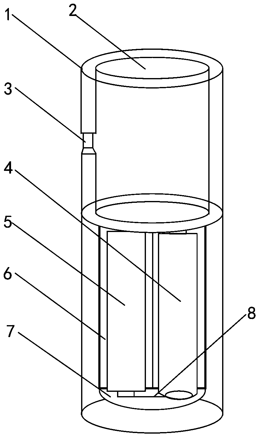
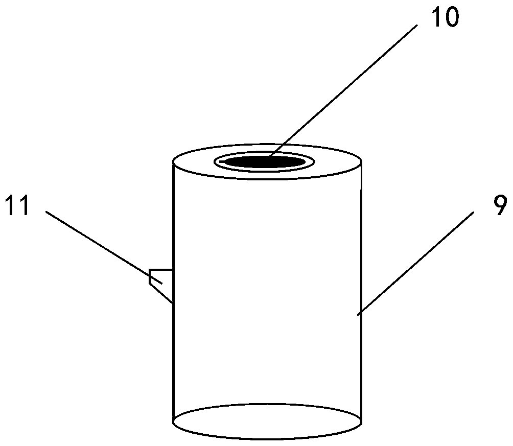
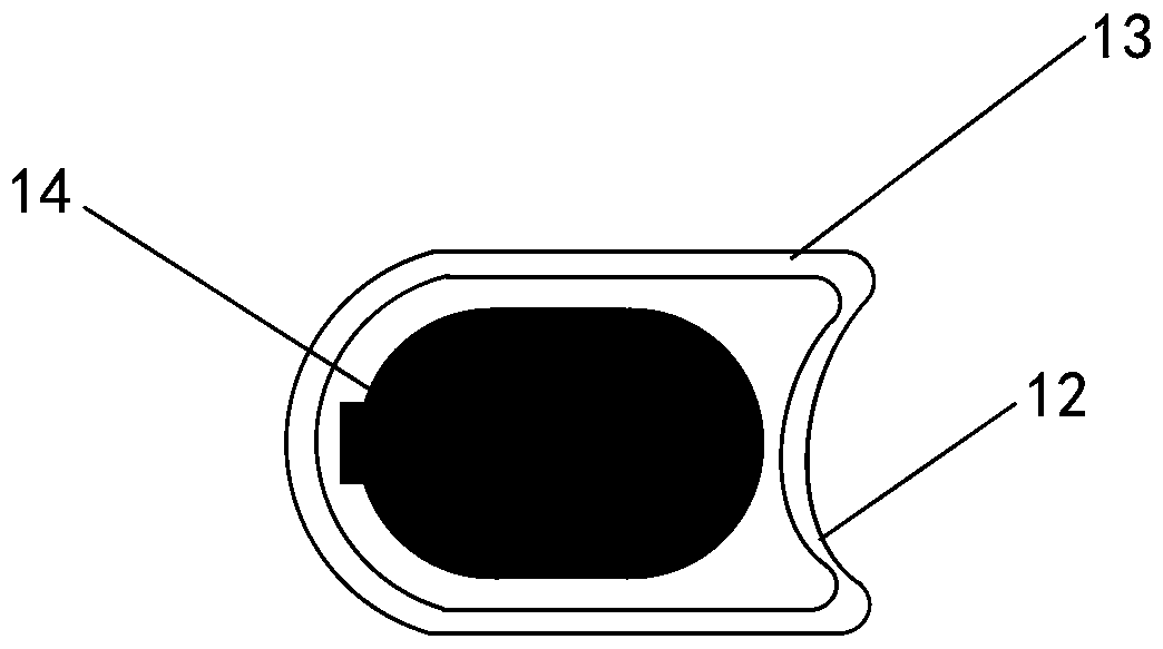
[0018] Embodiment one, such as Figure 1-4 As shown, in the ninety-five-type automatic rifle 15 accessory clip 16 inner cavity, install the positioning lock device 1, utilize the accessory clip lock cover groove 17 cover to insert the accessory clip lock cover 12 into it with the lock cover slot part, and put the inner The embedded lock cylinder 9 is inserted into the lock cavity 2 through the socket of the accessory clamp lock cover 12, and the lock tongue bayonet 3 in the middle of the lock cavity 2 blocks the lock tongue 11, forming an accessory clamp lock cover 12 to seal the positioning lock device 1, and the positioning lock device 1 The height is the same as the height of the inner cavity of the accessory clip 16 of the automatic rifle 15, the positioning lock device 1 does not exceed the position of the accessory clip lock cover groove 17, and is flush with the lower edge of the accessory clip lock cover groove 17, ensuring that the positioning lock device 1 is in the a...

Embodiment 2

[0019] Embodiment two, such as Figure 1-4 As shown, use the key to open the built-in lock cylinder 9 and pull it out, move out the automatic rifle 15 accessory clip lock cover 12, you can take out the positioning lock device 1, after replacing the seventh battery A4 and the seventh battery B5 on the positioning module 6, press Reinstall in reverse order of disassembly.


PUM


Abstract

The invention discloses a rifle internally-installed positioning lock which comprises a positioning lock device, an embedded type lock cylinder, an accessory clamp lock cover and an automatic rifle. The positioning lock device is embedded into an accessory clamp of the automatic rifle, then the accessory clamp lock cover and the embedded type lock cylinder are used for locking the positioning lockdevice into the accessory clamp of the automatic rifle, under the conditions that the original structure of the automatic rifle is not damaged, and the using performance of the rifle is not influenced, the positioning lock device is fixed and locked, the positioning lock device is conveniently detached and simply installed, a positioning module on the positioning lock device emits pulsed signalsor wireless signals to achieve rifle precise positioning, the problem that management of the rifle being on duty is difficult is mainly solved, and the events that the rifle is robbed or a sentry being on duty runs away with the rifle are effectively prevented.

Description

technical field [0001] The patent of the present invention relates to a built-in positioning lock, in particular to a built-in positioning lock for a firearm. Background technique [0002] Guns on duty are military equipment that the army focuses on control and safety precautions. The safety of guns is related to social security and stability and the overall construction of the army. However, the management of guns on duty has always been a difficult point. Incidents of guns being robbed and sentries on duty leaving with guns have occurred from time to time, causing social harm and great social impact. [0003] The current gun locators on the market are mainly used to install anti-tamper locators on the outside of the gun or place the locator in the accessory clip. The main disadvantages are as follows: First, the locator is bound outside the gun, which affects the use and performance of the gun. At the same time, it also affects the appearance of the gun. Second, although ...

Claims


Application Information

Patent Timeline
Patent Type & Authority Applications(China)
IPC IPC(8): F41A3/64
CPCF41A3/64
Inventor 叶建铜
Owner 南京佳普科技有限公司
Features
  • Generate Ideas
  • Intellectual Property
  • Life Sciences
  • Materials
  • Tech Scout
  • Unparalleled Data Quality
  • Higher Quality Content
  • 60% Fewer Hallucinations
Learn More