Mouth cavity orthodontic planting body anchorage three-dimensional image navigation locating method and special equipment thereof

A technology of three-dimensional imaging and special device, applied in dental implants, clinical application of radiological diagnosis, medical science, etc., to achieve the effect of reducing trauma and risk, low production cost, and improving accuracy

Inactive Publication Date: 2008-08-27
NANJING MEDICAL UNIV
View PDF0 Cites 31 Cited by
  • Summary
  • Abstract
  • Description
  • Claims
  • Application Information

AI Technical Summary

Problems solved by technology

[0009] Aiming at the problems in the prior art, the present invention firstly discloses a three-dimensional image navigation and positioning method for orthodontic implant anchorage, which utilizes a medical CT machine to perform maxillary and maxillary Computed tomography scan of bone and dentition; three-dimensional image reconstruction of CT scan data of patient's upper and lower jaw and dentition by using implant anchorage navigation software before operation, so as to determine the implant site, direction, depth and surgical During the operation, the surgical space and the image space are combined by matching the anatomical marker points on the teeth adjacent to the surgical area with the corresponding marker points determined in the 3D reconstruction image; and then using the infrared camera lens Transmit or receive infrared rays, determine the specific position of the device by tracking the position of the infrared reflective ball on the orthodontic implant anchorage positioning device, and send the signal back to the computer, and then use the connected mechanical arm to adjust the orientation of the positioning device, so that It meets the preoperative design requirements

Method used


Image

  • Mouth cavity orthodontic planting body anchorage three-dimensional image navigation locating method and special equipment thereof
  • Mouth cavity orthodontic planting body anchorage three-dimensional image navigation locating method and special equipment thereof

Examples


Embodiment Construction

[0017] The specific embodiment of the present invention is described in detail below in conjunction with accompanying drawing:

[0018] Firstly, using a medical CT machine, a computed tomography scan of the upper and lower jaws and dentition is performed on patients who need orthodontic implant anchorage.

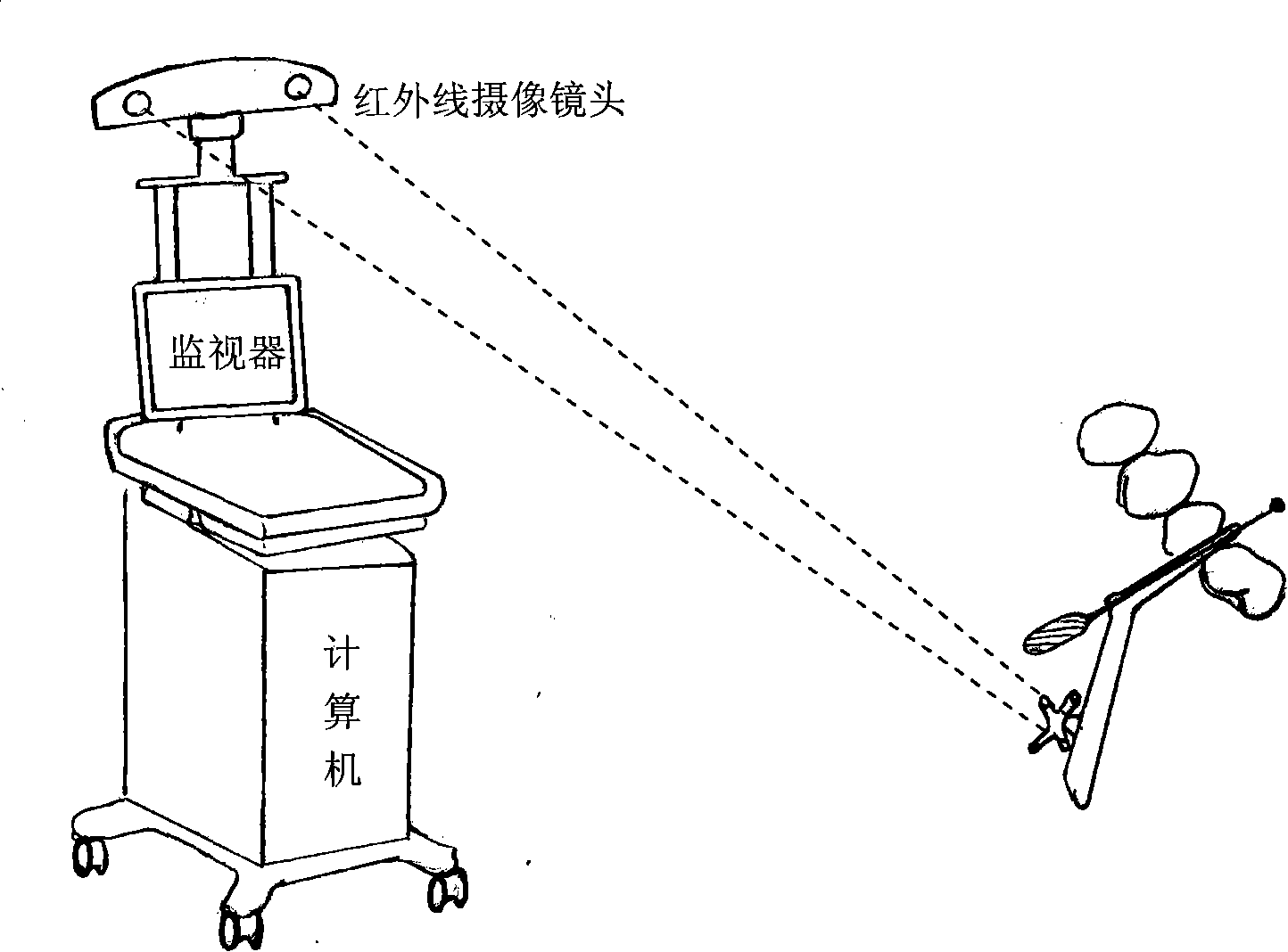
[0019] Such as figure 2 Shown, the concrete orthodontic implant anchorage implantation navigation situation in the operation process of the present invention

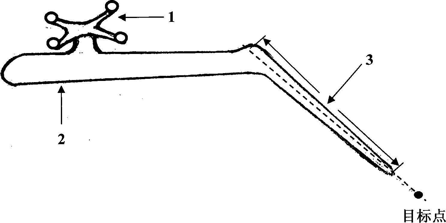
[0020] Before the operation, the implant anchorage navigation software was used to reconstruct the CT scan data of the patient's upper and lower jaws and dentition, and convert and store them in the computer. At this point, clinicians can use the software to perform a series of preoperative preparations and plan designs on the reconstructed images of the implant area to determine the implant site, direction, depth, and marker points required for intraoperative image registration. Based on this, the three-dimension...


PUM


Abstract

The invention discloses a method for navigation and positioning of an implant anchorage in orthodontics based on three-dimensional imaging and a dedicated device thereof. The invention utilizes the existing three-dimensional navigation system for orthodontic implants to design a novel positioning device for implant anchorages. An infrared camera is used to emit or receive infrared rays to trace the position of an infrared reflection sphere on the positioning device for orthodontic implant anchorages, thereby determining the exact position of the device; and simultaneously signals are transmitted to a computer to display the position of the positioning device on a preoperative or intraoperative image data of a patient. Based on the software-aided comparison with the predetermined three-dimensional position of the positioning device before operation, the position of the positioning device is regulated by using a linked mechanical arm to meet the requirement of preoperative design. After locating in the desired position, the device can accurately implant the implant anchorage at the desired depth in the desired direction.

Description

1. Technical field [0001] The invention relates to a medical device, in particular to a three-dimensional image navigation and stereotaxic device for implant anchorage used in orthodontic treatment. 2. Background technology [0002] In orthodontic treatment, correct anchorage design, control and application are important factors to achieve good orthodontic effects. The anchorage technology based on the classic orthodontic concept in the square wire arch correction technology has played a key role in the development of various orthodontic correction technologies. [0003] The so-called "anchorage" is to keep the teeth that do not want to move during the correction process. At present, there are a variety of anchorage enhancement devices for orthodontists to choose clinically, but none of them can fully meet the requirement of anchorage teeth not moving. Therefore, in some cases of severe crowding or heavy deep coverage without loss of anchorage, the improvement of tooth ali...

Claims


Application Information

Patent Timeline
Patent Type & Authority Applications(China)
IPC IPC(8): A61B6/14A61C8/00
Inventor 严斌王林鲍旭东陈国志汤文成
Owner NANJING MEDICAL UNIV
Why Eureka
Try Eureka