Pneumatic multi-nozzle complex tissue and organ manufacturing system with multiple degrees of freedom

A technology of complex structure and manufacturing system, applied in the direction of processing and manufacturing, manufacturing tools, additive manufacturing, etc., can solve the problems of low forming efficiency, non-replacement, and inability to spray the side surface of the formed body, and achieve the effect of high precision and convenient manufacturing.

Inactive Publication Date: 2013-12-11
TSINGHUA UNIV
View PDF7 Cites 31 Cited by
  • Summary
  • Abstract
  • Description
  • Claims
  • Application Information

AI Technical Summary

Problems solved by technology

[0013] ①The forming table can only rely on the three-dimensional motion device to move, and the position parameters are controlled by the X-axis and Y-axis perpendicular to each other when processing circular section and ring section materials, and the accuracy needs to be improved
[0014] ②The fixed nozzles are all screw extrusion type and cannot be replaced. There are structural disadvantages in cell assembly or printing processing, and it is impossible to accurately control the number of cells printed, the thickness of the cell layer and the exact position
[0015] ③The forming efficiency is low. The diameter of the slurry sprayed by the motor-assisted rapid prototyping nozzle depends on the diameter of the nozzle. The diameter of the nozzle is generally micron. huge, long working hours
[0017] ⑤ It is impossible to spray the side surface of the forming body. The motor-assisted rapid prototyping nozzle needs to be installed vertically. If it is installed horizontally, the slurry will drip under its own gravity after being extruded from the nozzle, and cannot be sprayed on the side of the forming body. surface attachment

Method used


Image

  • Pneumatic multi-nozzle complex tissue and organ manufacturing system with multiple degrees of freedom
  • Pneumatic multi-nozzle complex tissue and organ manufacturing system with multiple degrees of freedom
  • Pneumatic multi-nozzle complex tissue and organ manufacturing system with multiple degrees of freedom

Examples


Embodiment Construction

[0036] In order to further understand the technical solutions of the present invention, the present invention will be further described in detail below with reference to the accompanying drawings and examples.

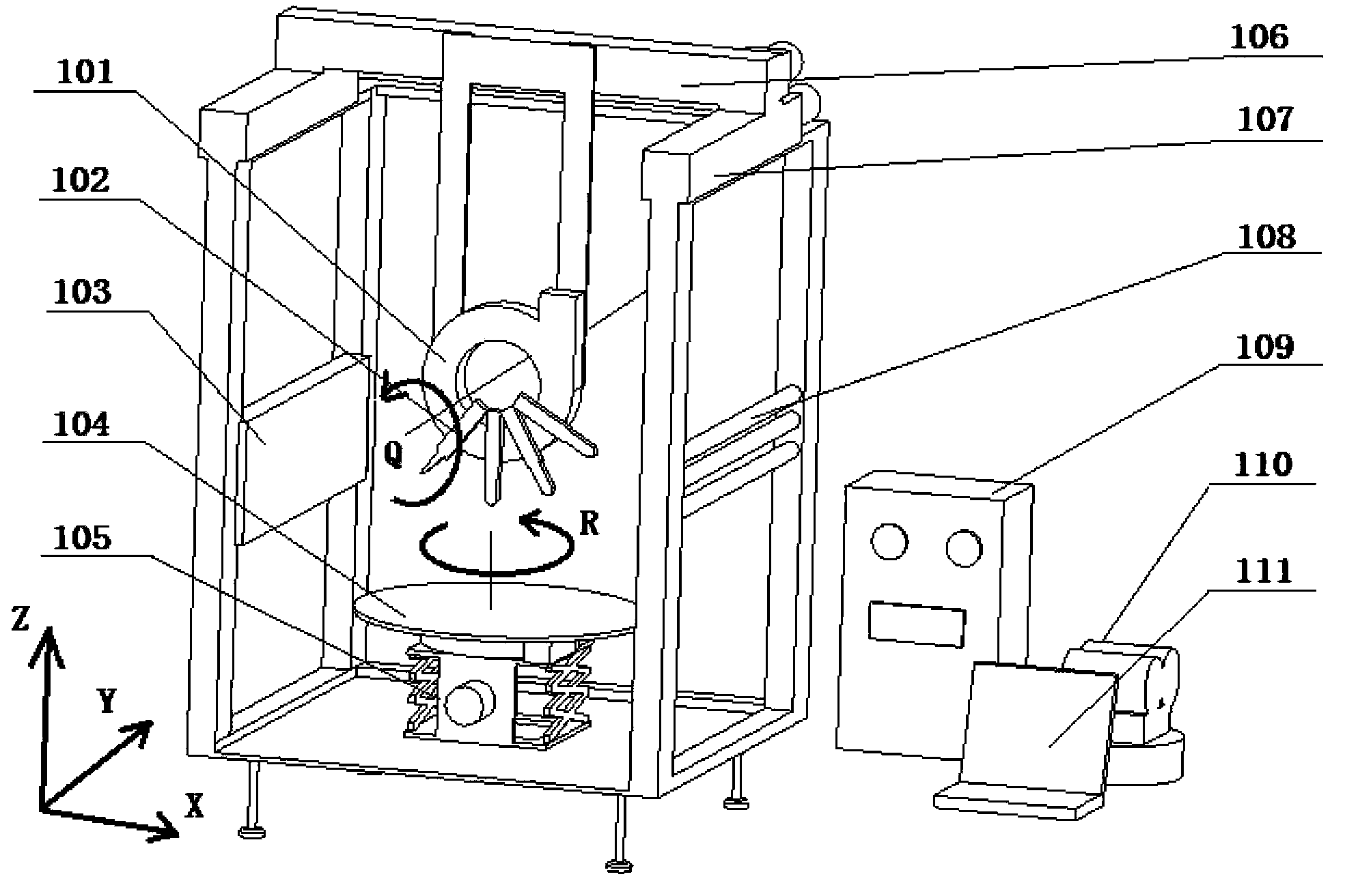
[0037] figure 1It is a schematic diagram of the structural principle of a multi-degree-of-freedom pneumatic multi-nozzle complex tissue and organ manufacturing system of the present invention. The system includes an X-direction movement mechanism 106, a Y-direction movement mechanism 107, a Q-direction rotation mechanism 101 that rotates around the Y-axis, a housing, Lifting platform 105, rotating forming platform 104, high-pressure gas source 110, multi-nozzle forming unit 102, spray solution pressure tank 209, temperature control device 103, sterilizing device 108, electrical control cabinet 109 and control unit 111.

[0038] The Q-direction rotating mechanism 101 rotating around the Y-axis, the lifting table 105, the rotary forming table 104, the multi-nozzle formin...


PUM


Abstract

The invention relates to a pneumatic multi-nozzle complex tissue and organ manufacturing system with multiple degrees of freedom, belonging to the field of organ manufacturing. The system comprises an X-direction movement mechanism, a Y-direction movement mechanism, a Q-direction rotation mechanism, a lifting platform, a rotary forming table, a shell, a high-pressure air source, a multi-nozzle forming unit, a spray solution pressure tank, a temperature control device, a sterilization device and a control unit. Under the control of the control unit, the multi-nozzle unit moves according to the set path and can spray according to the set sequence, so that the forming size is wide in cover range; the relative angle formed between a center shaft of a spray valve and the surface of the rotary forming table can be changed, so that a complex curved surface can be conveniently manufactured. The system enables multiple cells and support materials to be arranged at the corresponding positions for once according to the computer instruction, and various subsequent processing processes can be completed at the same time; the formed three-dimensional structure is directly connected with the corresponding circulating system in vivo, and various physiological functions of the complex tissues and organs can be rapidly realized.

Description

technical field [0001] The invention belongs to the technical field of tissue and organ manufacturing, in particular to a multi-degree-of-freedom pneumatic multi-nozzle complex tissue and organ manufacturing system. Background technique [0002] The rapid prototyping technology that came out in the late 1980s, as an important member of advanced manufacturing technology, gradually entered the field of stent forming. The new additive process created by it provided a new idea for solving the problems existing in the traditional stent forming technology. . Massachusetts Institute of Technology in the United States, Carnegie Mellon University, University of Michigan, National University of Singapore and Tsinghua University in China are all engaged in research work in this area. Among them, some researchers use the existing rapid prototyping process equipment and scaffold materials to form directly, such as the research group of D. Hutmacher of the National University of Singapor...

Claims


Application Information

Patent Timeline
Patent Type & Authority Applications(China)
IPC IPC(8): A61F2/02
CPCB33Y30/00B33Y80/00B29C64/118B29C64/106B29K2105/0073B29L2031/7532
Inventor 王小红刘利彪
Owner TSINGHUA UNIV
Why Eureka
Try Eureka