Pipe cutting equipment with supporting function

A technology for pipe cutting and equipment, applied in the field of pipes, can solve the problems of wasting time and materials, inability to cut off gas-filled pipes, and uneven cutting surfaces, and achieve the effect of improving safety.

Inactive Publication Date: 2018-04-13
丁文海
View PDF6 Cites 6 Cited by
  • Summary
  • Abstract
  • Description
  • Claims
  • Application Information

AI Technical Summary

Problems solved by technology

[0003] In order to obtain a suitable length for the pipeline before installation, it is generally necessary to cut it. In the prior art, it is generally cut with a hand-held cutting machine. However, due to the limitation of the diameter of the blade, the gas filling pipeline cannot be cut once. In order to cut off permanently, the pipe needs to be continuously rotated to cut off, resulting in the unevenness of the truncated surface and the need for subsequent rest, thus wasting more time and materials; at the same time, the cut pipe will lose its restrictive effect and fall down. There is a certain risk of injury to the operator

Method used


Image

  • Pipe cutting equipment with supporting function
  • Pipe cutting equipment with supporting function
  • Pipe cutting equipment with supporting function

Examples


Embodiment Construction

[0018] The following will clearly and completely describe the technical solutions in the embodiments of the present invention with reference to the accompanying drawings in the embodiments of the present invention. Obviously, the described embodiments are only some, not all, embodiments of the present invention. Based on the embodiments of the present invention, all other embodiments obtained by persons of ordinary skill in the art without making creative efforts belong to the protection scope of the present invention.

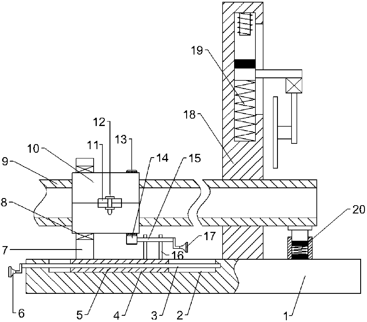
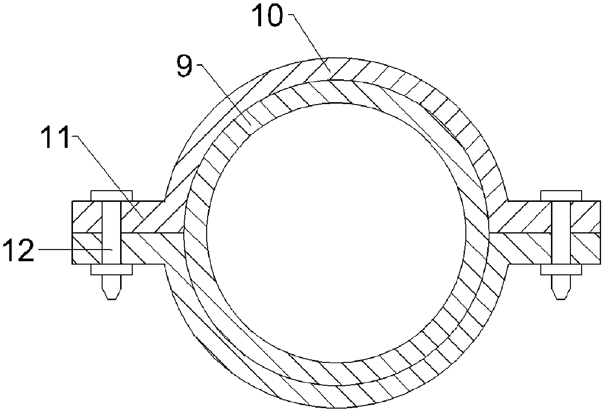
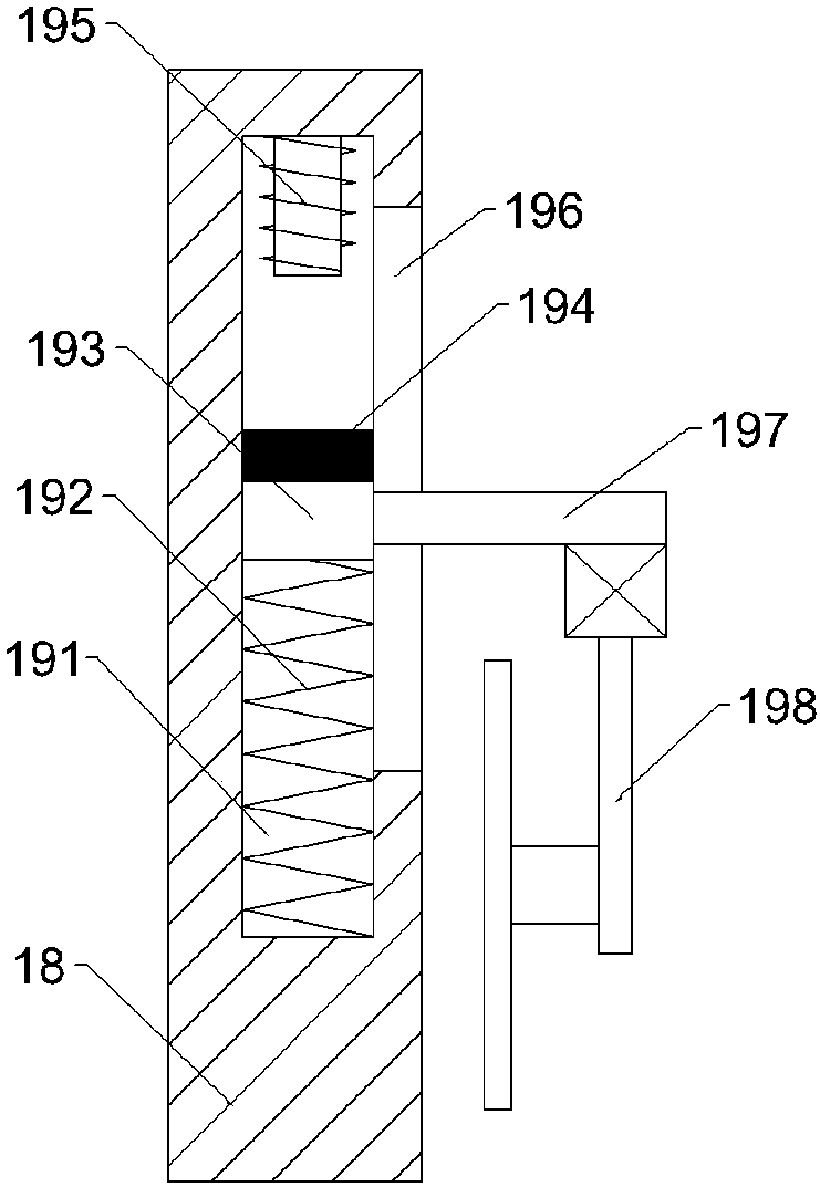
[0019] see Figure 1-Figure 4 , in an embodiment of the present invention, a pipe cutting equipment with a support function includes a base 1, a groove 2 is opened on the base 1, a moving plate 4 is arranged in the groove 2, and a horizontal threaded passage is opened on the moving plate 4. Hole 5, horizontal threaded through hole 5 is internally threaded with a threaded rod 3, the left end of the threaded rod 3 extends to the left side of the base 1, the left...


PUM


Abstract

Pipe cutting equipment with a supporting function comprises a base. A groove is formed in the base. A movable plate is arranged in the groove. A horizontal threaded through hole is formed in the movable plate. A threaded rod is connected into the horizontal threaded through hole in a threaded mode. The left end of the threaded rod extends to the left side of the base. A first handle is fixedly connected with the left end of the threaded rod. A first supporting plate is fixedly connected with the upper side of the movable plate. A ball bearing is arranged in the first supporting plate. A pipe clamping device is arranged in the ball bearing and comprises two semicircular sleeves. Flanges are fixedly arranged on the edges of the sleeves correspondingly. The flanges of the two sleeves are connected through locking bolts. A pipe is arranged in the two sleeves. The pipe cutting equipment has the beneficial effects that the two sleeves are fixed together through the locking bolts, relative fixing of the pipe and the sleeves is achieved, and then the left portions of the sleeves are fed into the ball bearing in the first supporting plate.

Description

technical field [0001] The invention relates to the technical field of pipelines, in particular to equipment for cutting pipelines with a supporting function. Background technique [0002] A pipeline is a device used to transport gas, liquid or fluid with solid particles connected by pipes, pipe connectors and valves. Usually, after the fluid is pressurized by blowers, compressors, pumps and boilers, it flows from the high-pressure part of the pipeline to the low-pressure part, and it can also be transported by the pressure or gravity of the fluid itself. Pipes are widely used, mainly in water supply, drainage, heat supply, gas supply, long-distance transportation of oil and natural gas, agricultural irrigation, hydraulic engineering and various industrial devices. [0003] In order to obtain a suitable length for the pipeline before installation, it is generally necessary to cut it. In the prior art, it is generally cut with a hand-held cutting machine. However, due to the...

Claims


Application Information

Patent Timeline
Patent Type & Authority Applications(China)
IPC IPC(8): B23Q3/06B23Q5/28
CPCB23Q3/06B23Q5/28
Inventor 丁文海
Owner 丁文海
Why Eureka
Try Eureka