Intelligent control system of thermal power unit

An intelligent control system, a technology for thermal power units, applied in control systems, control combustion, combustion methods, etc., can solve the problems of poor control logic adaptability, control logic adaptability and automation reduction, and increased labor intensity of power equipment operators. The effect of reducing system cost, reducing operation burden, and increasing service life

Active Publication Date: 2018-04-13
李吉宁 +1
View PDF5 Cites 6 Cited by
  • Summary
  • Abstract
  • Description
  • Claims
  • Application Information

AI Technical Summary

Problems solved by technology

[0002] The control system of thermal power units is mainly distributed control system (Distributed Control System, DCS), and the following defects exist in the control logic of the current DCS system, which makes it not sensitive enough to the tracking speed of AGC response:
[0003] 1. The control logic has poor adaptability to the external environment. Once the working condition of the power equipment deteriorates or the operator operates improperly, the control performance of the DCS system will deteriorate
[0004] 2. The modification of the control logic needs to be carried out when the power equipment is stopped
[0005] 3. It is difficult to modify the control logic to meet the requirements of power equipment operators and thermal workers
[0006] 4. After the power equipment is aged or transformed, the adaptability and automation of the control logic are reduced, resulting in an increase in the labor intensity of the power equipment operator
[0007] 5. After adding a new control target, the control logic cannot adapt to the new working environment, which in turn increases the labor intensity of the power equipment operator
For example, the overheating of the wall temperature can only be adjusted by the manual intervention of the operator. Once the intervention is not timely, the wall temperature overheating will occur frequently, which will affect the safety of the thermal power unit.

Method used


Image

  • Intelligent control system of thermal power unit
  • Intelligent control system of thermal power unit
  • Intelligent control system of thermal power unit

Examples


Embodiment Construction

[0043] Hereinafter, preferred embodiments of the present invention will be described with reference to the drawings. Those skilled in the art should understand that these embodiments are only used to explain the technical principles of the present invention and are not intended to limit the protection scope of the present invention.

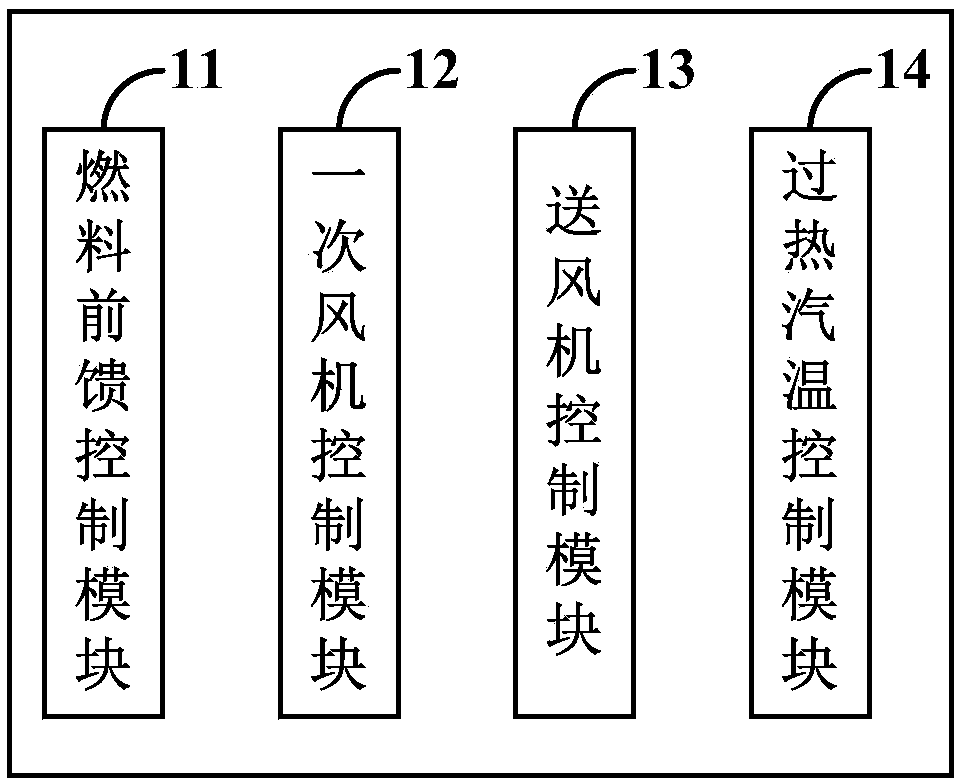
[0044] See attached figure 1 , figure 1 Illustratively shows the structure diagram of the intelligent control system of the thermal power unit in this embodiment. Such as figure 1 As shown, the intelligent control system of the thermal power unit in this embodiment may include a fuel feedforward control module 11, a primary fan control module 12, a blower control module 13, and a superheated steam temperature control module 14. Wherein, the fuel feedforward control module 11 is configured to adjust the fuel control bias amount according to the load state, and modify the fuel control target value according to the adjusted fuel control bias amount. T...


PUM


Abstract

The invention relates to the field of intelligent control on power equipment, provides an intelligent control system of a thermal power unit, and aims to solve the technical problem about the way to control the thermal power unit to quickly and stably track an AGC response. A fuel feed-forward control module of the control system can adjust the fuel control offset according to the load state and can correct the fuel control target value according to the adjusted fuel control offset. A primary fan control module can adjust the primary fan opening degree offset according to the fuel quantity state. An air supply fan control module can adjust the air supply fan opening degree offset according to the fuel quantity state. A superheated steam temperature control module can adjust the de-superheating water regulating valve opening degree according to the temperature information of the thermal power unit. According to the technical scheme, the fuel feed-forward control module, the primary fancontrol module, the air supply fan control module and the superheated steam temperature control module have the synergistic effect, the combustion inertia of the thermal power unit can be overcome, the load can be increased and decreased quickly, the load changing rate can be effectively controlled, and load overcorrection can be prevented.

Description

Technical field [0001] The invention relates to the field of intelligent control of electric power equipment, in particular to an intelligent control system of a thermal power unit. Background technique [0002] The control system of the thermal power unit is mainly a distributed control system (Distributed Control System, DCS), and the current control logic of the DCS system has the following defects, resulting in its insufficient tracking speed of the AGC response: [0003] 1. The control logic has poor adaptability to the external environment. Once the working conditions of the power equipment deteriorate or the operator's improper operation occurs, the control performance of the DCS system will deteriorate. [0004] 2. The modification of the control logic needs to be carried out when the power equipment is stopped. [0005] 3. It is difficult to modify the control logic to meet the requirements of electric equipment operators and thermal workers. [0006] 4. After the power equipm...

Claims


Application Information

Patent Timeline
Patent Type & Authority Applications(China)
IPC IPC(8): F22B35/00F23N1/04
CPCF22B35/00F23N1/042
Inventor 李吉宁姜剑波
Owner 李吉宁
Why Eureka
Try Eureka