
Method and device for testing tilt of camera module

A technology of camera module and testing method, which is applied in image communication, television, electrical components, etc., can solve problems such as low test accuracy, recognition failure or analysis error, and limited application scenarios, so as to avoid errors or test failures and improve Test accuracy and stability, and test the effect of a wide range of scenarios

Active Publication Date: 2018-04-17
GUANGDONG OPPO MOBILE TELECOMM CORP LTD
View PDF4 Cites 5 Cited by
  • Summary
  • Abstract
  • Description
  • Claims
  • Application Information

AI Technical Summary

Problems solved by technology

This method can only use specific test charts, the application scenarios are relatively limited, and it involves hypotenuse recognition and analysis, which is prone to recognition failure or analysis error, low test accuracy and poor stability

Method used


Image

  • Method and device for testing tilt of camera module
  • Method and device for testing tilt of camera module
  • Method and device for testing tilt of camera module

Examples


Embodiment Construction

[0030] Referring to the drawings, wherein the same reference numerals represent the same components, the principles of the present application are exemplified by being implemented in a suitable computing environment. The following description is based on illustrated specific embodiments of the present application, which should not be construed as limiting other specific embodiments of the present application that are not described in detail here.

[0031] In the following description, specific embodiments of the present application will be described with reference to steps and symbols executed by one or more computers, unless otherwise stated. Accordingly, these steps and operations will several times be referred to as being computer-implemented, which herein refers to operations by a computer processing unit of electronic signals representing data in a structured form. This operation transforms the data or maintains it at a location in the computer's memory system that can re...


PUM


Abstract

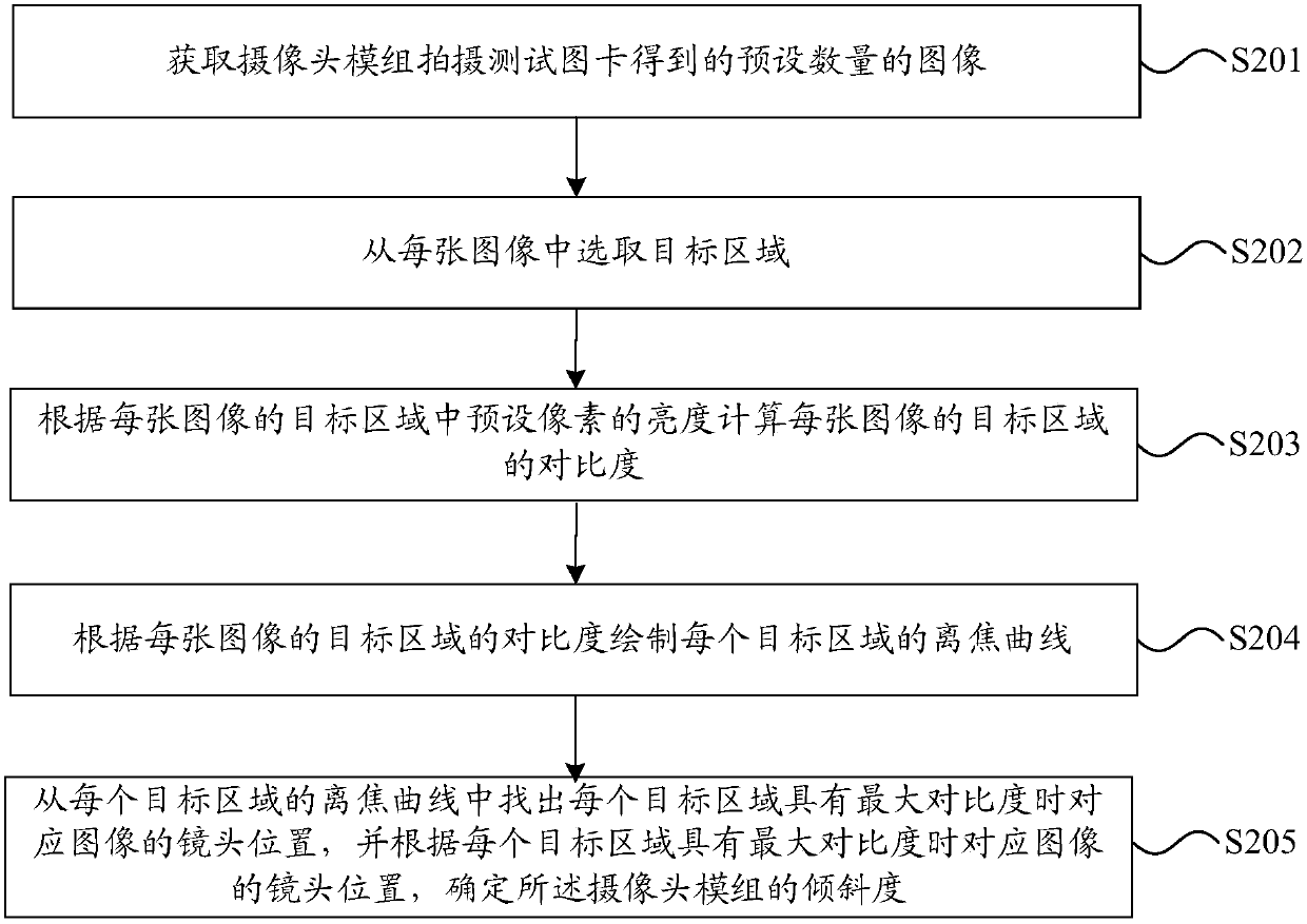
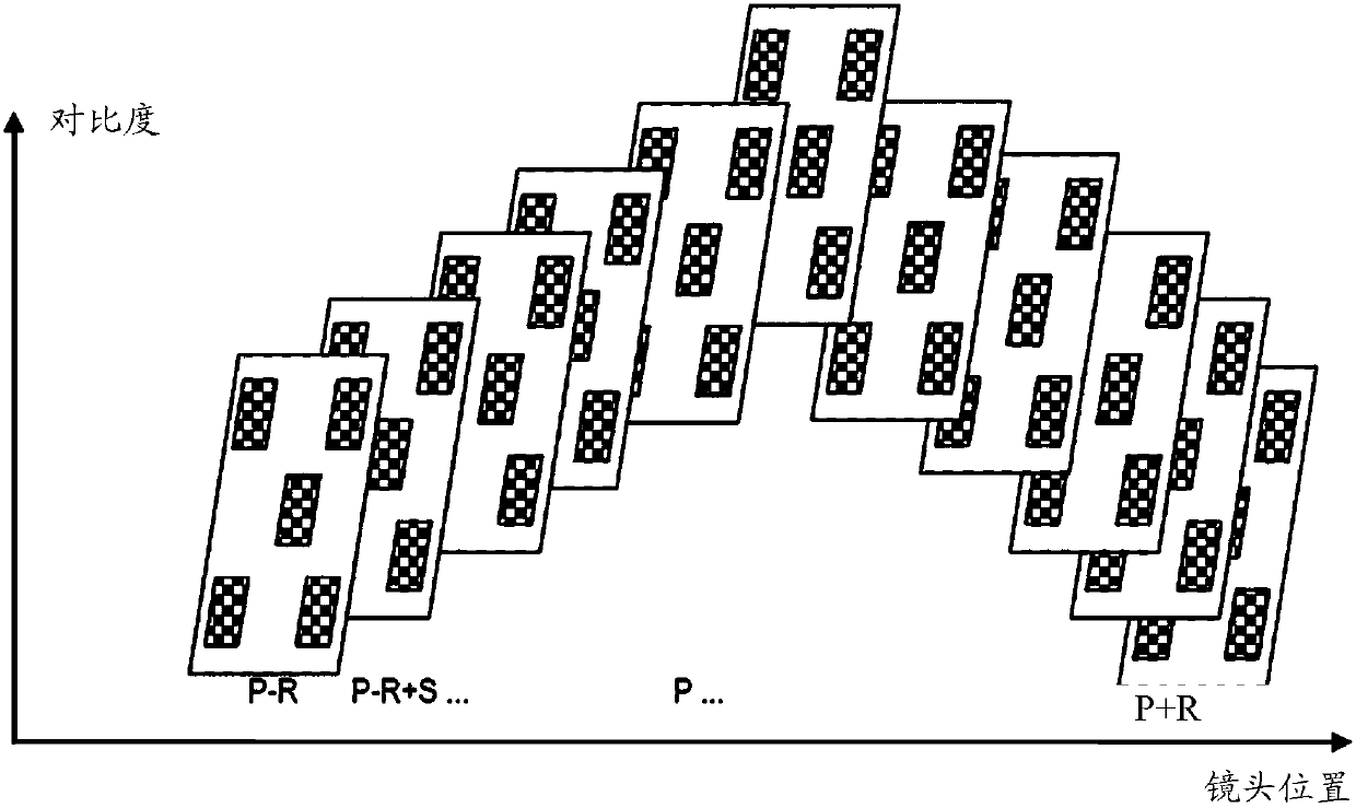
The embodiment of the invention discloses a method and device for testing the tilt of a camera module. The method for testing the tilt comprises the following steps: obtaining a preset number of images obtained by the camera module by shooting a test picture card; selecting a target area from each image; calculating a contrast ratio of the target area of each image according to the brightness of apreset pixel in the target area of each image; drawing a defocus curve of each target area according to the contrast ratio of the target area of each image; and finding a lens position of corresponding to the image when each target area has the maximum contrast ratio from the defocus curve of each target area, and determining the tilt of the camera module according to the lens position of corresponding to the image when each target area has the maximum contrast ratio. The method provided by the embodiment of the invention is applied to wide test scenes and can improve the accuracy and stability of the test.

Description

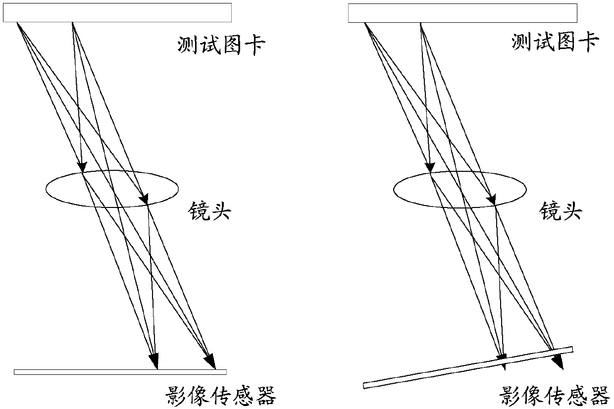
technical field [0001] The present application relates to the field of camera module testing, in particular to a method and device for testing the inclination of a camera module. Background technique [0002] During the production process of the camera module, due to the influence of manufacturing and assembly technology or process, there will be non-parallel conditions between the lens and the image sensor in the camera module, that is, there is a certain degree of inclination between the lens and the image sensor. When such a camera module is working, defocusing will occur, resulting in blurred images and poor image quality. Therefore, before leaving the factory, it is necessary to detect the degree of inclination between the lens and the image sensor to ensure product quality. [0003] Existing detection methods are mainly by taking a specific test chart (hypotenuse test chart), and performing hypotenuse recognition and analysis on the captured image to obtain the spatia...

Claims


Application Information

Patent Timeline
IPC IPC(8): H04N17/00
Inventor 张乐
Owner GUANGDONG OPPO MOBILE TELECOMM CORP LTD
Learn More