
Force transfer device for use with a valve train and method of manufacture

A technology of valve mechanism and force, applied in the direction of valve device, valve driving device, mechanical equipment, etc.

Active Publication Date: 2021-01-12
EATON CORP
View PDF1 Cites 0 Cited by
  • Summary
  • Abstract
  • Description
  • Claims
  • Application Information

AI Technical Summary

Problems solved by technology

[0006] However, since the rocker arm structure described above involves a needle bearing arranged between the support shaft and the roller, the shaft is subjected to a cam force through the needle bearing, which means that the support shaft is subjected to a local load

Method used


Image

  • Force transfer device for use with a valve train and method of manufacture
  • Force transfer device for use with a valve train and method of manufacture
  • Force transfer device for use with a valve train and method of manufacture

Examples


Embodiment Construction

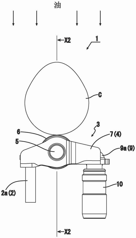
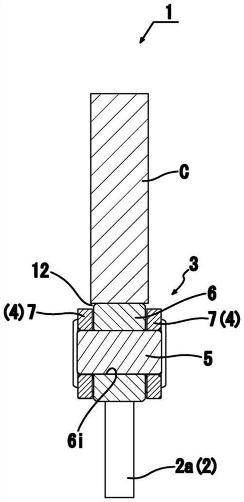
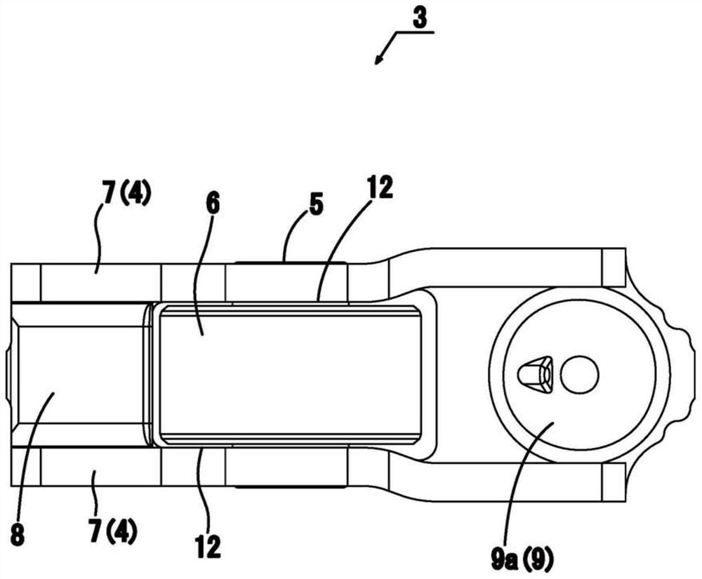
[0034]Hereinafter, examples of the present disclosure are explained in detail based on the accompanying drawings. refer to Figure 1 to Figure 9 Let's explain the first example of the present disclosure. In order to achieve the first purpose disclosed above, refer to Figure 1 to Figure 3 , a rocker arm structure for use with a valve train of an engine includes: an arm (4) for transmitting an action on the valve (2) to the action transmitting end of the arm (this end is called the action transmitting end) ) to open / close the force of the valve (2). The other end of the support shaft (5) towards the arm (4) protrudes laterally from the arm (4) at a position offset relative to said one end. A ring roller (6) is rotatably mounted on the outer periphery of the support shaft (5). The roller is rotated by the cam force applied to its outer circumference by the cam (C) to transmit the cam force to the support shaft (5) so as to transmit the cam force to the action transmitting en...


PUM


Abstract

The present invention discloses a force transmission device for use with a valve train of an engine, the force transmission device including a force transmission member that transmits force to a valve to open / close the valve. The support shaft is provided in the force transmission member. Ring rollers are mounted directly on the outer circumference of the support shaft. The roller is adapted to rotate when subjected to a cam force applied by the cam and to transmit the cam force as a force to the force transmitting member. The ratio d / D of the inner diameter d to the outer diameter D of the ring roll is not less than 0.7.

Description

[0001] Cross References to Related Applications [0002] This application claims the benefit of Japanese Patent Application No. 2015-118460 filed on June 11, 2015. The disclosures of the above applications are incorporated herein by reference. technical field [0003] The present disclosure relates to force transfer devices for use with valve trains and methods of making the same. Background technique [0004] In one prior art example, a typical rocker arm structure includes an arm for transmitting force to one end thereof (the end hereinafter referred to as the motion transmitting end), which is adapted to transmit motion to the valve for opening / closing the valve; a support shaft protruding laterally from the arm toward the other end of the arm at a position of the arm offset relative to said action transmitting end. The ring roller is rotatably mounted on the outer periphery of the support shaft through a rollable bearing equipped with a needle bearing, the ring roller...

Claims


Application Information

Patent Timeline
Patent Type & Authority Patents(China)
IPC IPC(8): F01L1/18F01L1/08
CPCF01L2810/02F01L2820/01F01L1/14F01L1/185F01L2305/00F01L2820/02F01L1/2405F01L2303/00F01L2305/02
Inventor 龟田美千广木森贵俊
Owner EATON CORP
Learn More