Component-mounting machine

A technology for mounting machines and components, applied in the direction of electrical components, electrical components, printed circuits, etc., can solve the problem of not being able to identify the guide cover and so on

Active Publication Date: 2018-04-17
FUJI KK
View PDF4 Cites 2 Cited by
  • Summary
  • Abstract
  • Description
  • Claims
  • Application Information

AI Technical Summary

Problems solved by technology

In this component mounting machine, when the tape feeder is installed on the feeder installation table, the empty tape discharged from the tape feeder is set to be exposed to the upper surface of the guide cover, or the tape feeder If the empty tape is exposed to the upper surface side of the guide cover by the tape feeding operation after the installation of the device, the image recognition unit cannot recognize the upper surface of the guide cover from the image captured by the camera.

Method used


Image

  • Component-mounting machine
  • Component-mounting machine
  • Component-mounting machine

Examples


Embodiment 1

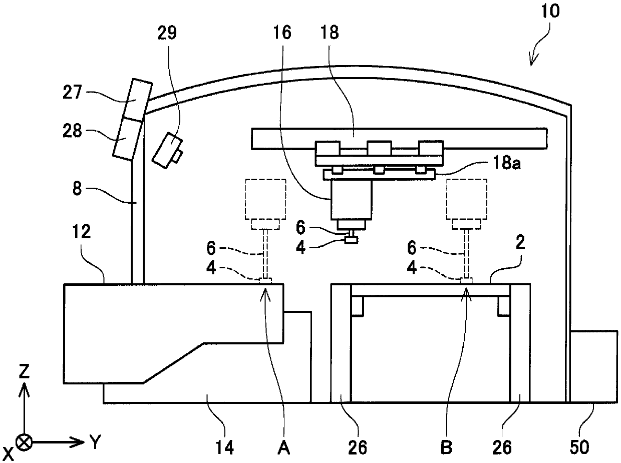
[0022] Hereinafter, the component mounting machine 10 of the first embodiment will be described. The component mounting machine 10 is a device for mounting the electronic component 4 on the circuit substrate 2 . The component mounter 10 is also called a surface mounter or a mounter. Usually, the component mounting machine 10 is installed in parallel with a solder printing machine, other component mounting machines, and a board inspection machine to form a series of mounting lines. In addition, the circuit substrate 2 includes, for example, a printed wiring board on which no electronic circuit components are mounted, a printed circuit board on which electronic circuit components are mounted and electrically bonded on one surface and has no electronic circuit components mounted on the other surface, or a printed circuit board on which a bare substrate is mounted. The chip also constitutes a base material of a substrate with a chip, a base material on which an electronic circuit...

Embodiment 2

[0035] Next, refer to Figure 4 , the component mounting machine 10a of the second embodiment will be described. Hereinafter, only points of difference from Embodiment 1 will be described, and detailed descriptions of the same configuration as Embodiment 1 will be omitted. The same applies to other examples.

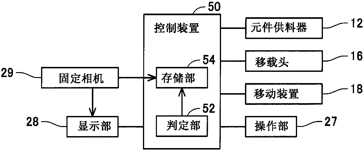
[0036] Such as Figure 4 As shown, the component mounting machine 10 a includes a detection unit 56 . The detection part 56 detects whether the component feeder 12 is attached to the component mounting machine 10a (feeder holding|maintenance part 14). The detection unit 56 is communicably connected to the control device 50 , and inputs the detection result of the detection unit 56 to the control device 50 . As the detection unit 56 , for example, a mechanism for detecting whether the fixed camera 29 recognizes the component feeder 12 or a mechanism for detecting the component feeder 12 by a sensor can be used.

[0037] The control device 50 displays an image capture...

Embodiment 3

[0039] Next, the component mounting machine of the third embodiment will be described. In the component mounting machine of the present embodiment, the control device 50 displays a captured image captured by the fixed camera 29 on the display unit 28 based on the operation of the operation unit 27 by the user. That is, the user can check the image of the inside of the component mounting machine at any point of time. Therefore, regardless of whether the component mounting machine is operating normally, the user himself can regularly grasp the internal state of the component mounting machine. Also in this embodiment, the structure of the fixed camera 29 is the same as that of the fixed camera of the first embodiment, and therefore the same operational effect as that of the component mounting machine of the first embodiment can be exhibited. In addition, the function of the operation unit 27 of the present embodiment can also be used in the component mounting machine 10a of the ...


PUM


Abstract

The invention provides, in a component-mounting machine (10) for mounting an electronic component (4) on a circuit substrate (2), a technique which can display a movable region inside the component-mounting machine (10) within the same image. This component-mounting machine (10) is provided with a fixed camera (29) for monitoring the interior of the component-mounting machine (10), and a display unit (28) that can display the image captured by the fixed camera (29). The fixed camera (29) can capture within the same image a range from the suction position at which a suction nozzle (6) suctionsan electronic component (4) supplied from a component feeder (12) to the mounting position at which the electronic component (4) is mounted on the circuit substrate (2).

Description

technical field [0001] This specification relates to a component mounting machine for mounting electronic components on a circuit board. Background technique [0002] Patent Document 1 discloses a component mounting machine for mounting electronic components on a circuit substrate. The component mounting machine is equipped with: a tape feeder; a guide cover that covers the upper part of the tape guide passage; a camera that can photograph the inspection area from above the guide cover; an image recognition unit that processes the image of the inspection area to perform image recognition; and The inspection unit performs a judgment based on the inspection. The tape guide path bends and guides the empty tape discharged from the tape feeder downward. In this component mounting machine, when the tape feeder is installed on the feeder installation table, the empty tape discharged from the tape feeder is set to be exposed to the upper surface of the guide cover, or the tape fee...

Claims


Application Information

Patent Timeline
Patent Type & Authority Applications(China)
IPC IPC(8): H05K13/08
CPCH05K13/0812H05K13/0409H05K13/0419H05K13/0813H05K13/0061H05K13/021Y10T29/53191Y10T29/53174H05K2203/163H05K13/083H05K3/303H05K13/087
Inventor 服部和真
Owner FUJI KK
Why Eureka
Try Eureka