Component Mounting Machine
A technology for installing machines and components, applied in the direction of electrical components, electrical components, printed circuits, etc., can solve the problem of not being able to identify the guide cover
- Summary
- Abstract
- Description
- Claims
- Application Information
AI Technical Summary
Problems solved by technology
Method used
Image
Examples
Embodiment 1
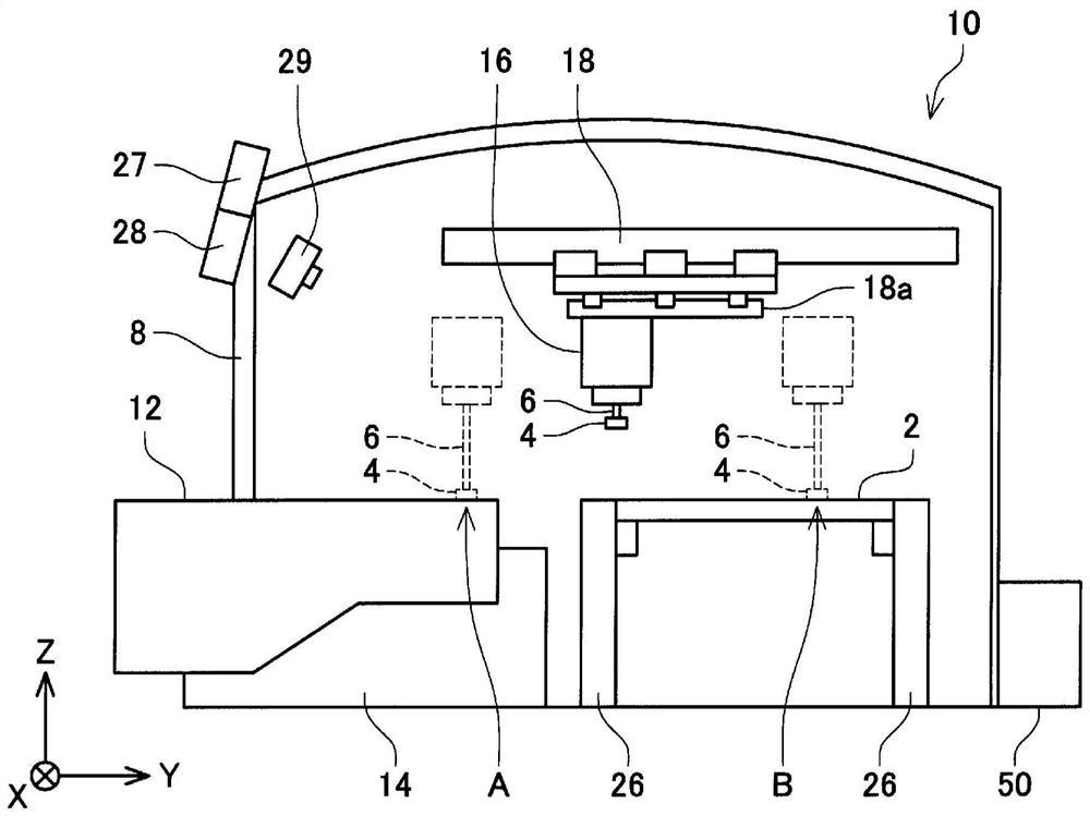
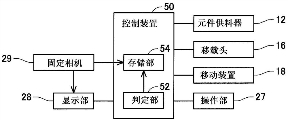
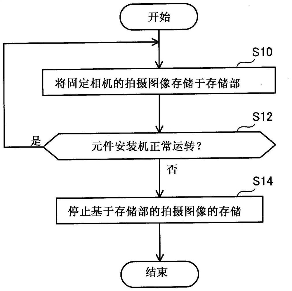
[0022] Hereinafter, the component mounting machine 10 of the first embodiment will be described. The component mounting machine 10 is a device for mounting the electronic component 4 on the circuit substrate 2 . The component mounter 10 is also called a surface mounter or a mounter. Usually, the component mounting machine 10 is installed in parallel with a solder printing machine, other component mounting machines, and a board inspection machine to form a series of mounting lines. In addition, the circuit base material 2 includes, for example, a printed wiring board on which no electronic circuit components are mounted, a printed circuit board on which electronic circuit components are mounted and electrically bonded on one surface and has no electronic circuit components mounted on the other surface, or a printed circuit board on which a bare substrate is mounted. The chip also constitutes a base material of a substrate with a chip, a base material on which an electronic cir...
Embodiment 2
[0035] Next, refer to Figure 4 , the component mounting machine 10a of the second embodiment will be described. Hereinafter, only points of difference from Embodiment 1 will be described, and detailed descriptions of the same configuration as Embodiment 1 will be omitted. The same applies to other examples.
[0036] Such as Figure 4 As shown, the component mounting machine 10 a includes a detection unit 56 . The detection part 56 detects whether the component feeder 12 is attached to the component mounting machine 10a (feeder holding|maintenance part 14). The detection unit 56 is communicably connected to the control device 50 , and inputs the detection result of the detection unit 56 to the control device 50 . As the detection unit 56 , for example, a mechanism for detecting whether the fixed camera 29 recognizes the component feeder 12 or a mechanism for detecting the component feeder 12 by a sensor can be used.
[0037] The control device 50 displays an image capture...
Embodiment 3
[0039] Next, the component mounting machine of the third embodiment will be described. In the component mounting machine of the present embodiment, the control device 50 displays a captured image captured by the fixed camera 29 on the display unit 28 based on the operation of the operation unit 27 by the user. That is, the user can check the image of the inside of the component mounting machine at any point of time. Therefore, regardless of whether the component mounting machine is operating normally, the user himself can regularly grasp the internal state of the component mounting machine. Also in this embodiment, the structure of the fixed camera 29 is the same as that of the fixed camera of the first embodiment, and therefore the same operational effect as that of the component mounting machine of the first embodiment can be exhibited. In addition, the function of the operation unit 27 of the present embodiment can also be used in the component mounting machine 10a of the ...
PUM
 Abstract
Description
Claims
Application Information
 - R&D
- Intellectual Property
- Life Sciences
- Materials
- Tech Scout
- Unparalleled Data Quality
- Higher Quality Content
- 60% Fewer Hallucinations
Browse by: Latest US Patents, China's latest patents, Technical Efficacy Thesaurus, Application Domain, Technology Topic, Popular Technical Reports.
© 2025 PatSnap. All rights reserved.Legal|Privacy policy|Modern Slavery Act Transparency Statement|Sitemap|About US| Contact US: help@patsnap.com


