Bulk particle conveying device

A technology for conveying devices and particles, which is applied in the direction of conveyor control devices, conveyors, conveyor objects, etc., and can solve problems such as inability to bend and turn, and conveying routes that can only be straight lines.

Active Publication Date: 2018-04-20
HUBEI OCEAN ENG EQUIP RES INST CO LTD
View PDF6 Cites 1 Cited by
  • Summary
  • Abstract
  • Description
  • Claims
  • Application Information

AI Technical Summary

Problems solved by technology

[0004] Aiming at the problems existing in the prior art, the embodiment of the present invention provides a bulk particle conveying device, which is used to solve the technical problem in the prior art that the conveying route of the belt conveyor can only be a straight line and cannot be bent.

Method used


Image

  • Bulk particle conveying device
  • Bulk particle conveying device
  • Bulk particle conveying device

Examples


Embodiment 1

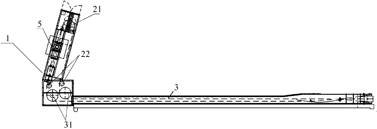
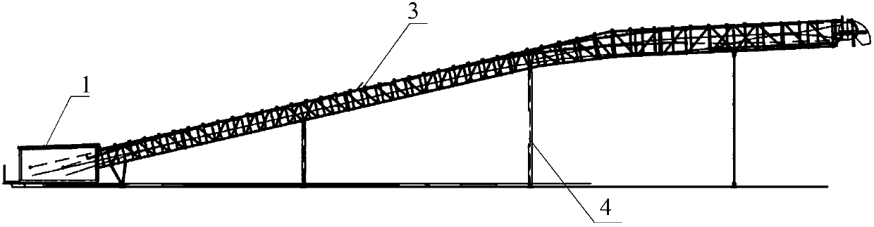
[0045] This embodiment provides a bulk particle conveying device, and the bulk particle may include: ore particles, food particles, metallurgical particles and feed particles, etc.; figure 1 As shown, the device includes: filling platform 1, steering mechanism 2, transmission mechanism 3; wherein,

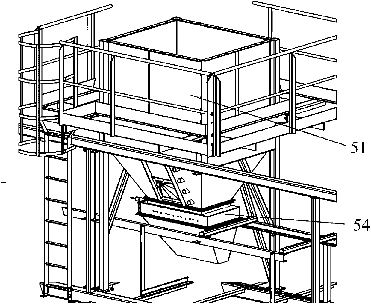
[0046] The filling platform 1 is provided with a steering mechanism 2, and the filling platform 1 is used for filling the bulk particles; specifically, see figure 1 , the device also includes a housing, the housing includes: a truss and a thin plate; the filling platform 1, the steering mechanism 2 and the transmission mechanism 3 are installed on the truss; the thin plate is installed on the The outside of the above-mentioned truss forms a closed space to avoid environmental pollution during the process of conveying materials, and in this way can also convey items that have requirements for the environment.

[0047] Here, both the filling platform 1 and the transmission mechanism...

Embodiment 2

[0066] In practical application, when utilizing the delivery device provided by Embodiment 1 to deliver fish feed, the details are as follows:

[0067] Such as figure 1 As shown, the device includes: filling platform 1, steering mechanism 2, transmission mechanism 3; wherein,

[0068] The filling platform 1 is provided with a steering mechanism 2, and the filling platform 1 is used for filling the bulk particles; specifically, see figure 1 , the device also includes a housing, the housing includes: a truss and a thin plate; the filling platform 1, the steering mechanism 2 and the transmission mechanism 3 are installed on the truss; the thin plate is installed on the The outside of the above-mentioned truss forms a closed space to avoid environmental pollution during the process of conveying materials, and in this way can also convey items that have requirements for the environment.

[0069] Here, both the filling platform 1 and the transmission mechanism 3 are provided with ...


PUM


Abstract

The invention provides a bulk particle conveying device. The device comprises an injecting platform and a steering mechanism, wherein the steering mechanism is arranged in the injecting platform; theinjecting platform is used for injecting bulk particles; and the steering mechanism is connected with a conveying mechanism through a belt, and is used for adjusting a conveying direction of the belt.Through reasonable setting of the position of the steering mechanism, the conveying direction can be randomly changed, so that steering of a conveying path can be guaranteed.

Description

technical field [0001] The invention belongs to the technical field of particle conveying, and in particular relates to a bulk material particle conveying device. Background technique [0002] As a short-distance conveying device for solid objects such as bulk materials and particles, belt conveyors are widely used in metallurgy, mining, construction, chemical, food production and other industries. [0003] Existing belt conveyors often spread the belt on the load-carrying member to bypass the first driving device and steering device for circular movement, and the granular items placed on the belt follow the belt movement by the friction between the belt and the conveyor belt. This structure results in a conveying path that can only be a straight line and cannot be bent. Contents of the invention [0004] Aiming at the problems existing in the prior art, the embodiment of the present invention provides a bulk particle conveying device, which is used to solve the technical...

Claims


Application Information

Patent Timeline
IPC IPC(8): B65G47/18B65G23/04B65G21/20B65G47/34B65G23/44B65G43/02
CPCB65G21/20B65G23/04B65G23/44B65G43/02B65G47/18B65G47/34B65G2203/042
Inventor 王宇徐春涛秦江平李伟锋张丽杰马会霞
Owner HUBEI OCEAN ENG EQUIP RES INST CO LTD
Why Eureka
Try Eureka