Cup-shaped furnace pipe special for combustion furnace
A cup-shaped and furnace technology, which is applied in the application, household heating, heating fuel and other directions, can solve the problem of no unified connecting plate device, etc., and achieve the effect of better cooking effect, increased explosive power and simple structure.
- Summary
- Abstract
- Description
- Claims
- Application Information
AI Technical Summary
Problems solved by technology
Method used
Image
Examples
Embodiment 1
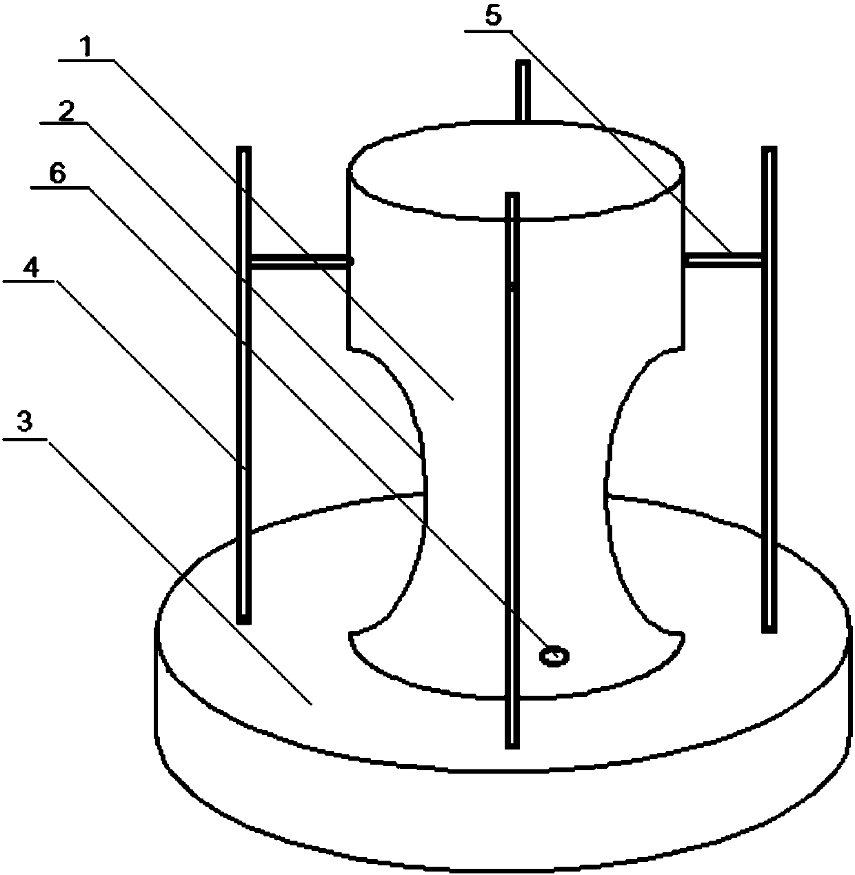
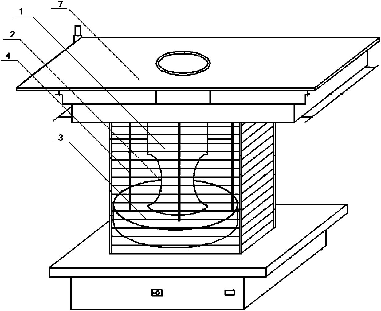
[0016] Embodiment 1: A special cup-shaped furnace for burning furnaces, the cup-shaped furnace body 1 is a cup-shaped cylinder made of metal plates, and the lower part of the cup-shaped furnace body 1 is a cup-shaped flash neck 2, The sudden fire neck 2 is installed on the oxygen supply chamber 3 of the burner, the upper part of the cup-shaped furnace body 1 is provided with a tempering channel, and the oxygen supply chamber 3 is provided with a secondary oxygen supply for the burner 7 and a furnace tempering channel supply The oxygen supply pipe hole 4 of oxygen, is provided with horizontal pipe 5 on the oxygen supply pipe hole 4 and is the cup-shaped furnace body 1, and the cup-shaped furnace body 1 is made of stainless steel.
Embodiment 2
[0017] Embodiment 2: A special cup-shaped furnace for burning furnaces, the cup-shaped furnace body 1 is a cup-shaped cylinder made of metal plates, and the lower part of the cup-shaped furnace body 1 is a cup-shaped flash neck 2, The sudden fire neck 2 is installed on the oxygen supply chamber 3 of the burner, the upper part of the cup-shaped furnace body 1 is provided with a tempering channel, and the oxygen supply chamber 3 is provided with a secondary oxygen supply for the burner 7 and a furnace tempering channel supply The oxygen supply tube hole 4 of oxygen, the oxygen supply tube hole 4 is provided with horizontal tube 5 and is the cup-shaped furnace body 1, and the cup-shaped furnace body 1 is made of white iron plate.
Embodiment 3
[0018] Embodiment 3: A special cup-shaped furnace for burning furnaces. The cup-shaped furnace body 1 is a cup-shaped cylinder made of metal plates. The lower part of the cup-shaped furnace body 1 is a cup-shaped flash neck 2. The sudden fire neck 2 is installed on the oxygen supply chamber 3 of the burner, the upper part of the cup-shaped furnace body 1 is provided with a tempering channel, and the oxygen supply chamber 3 is provided with a secondary oxygen supply for the burner 7 and a furnace tempering channel supply The oxygen supply pipe hole 4 of oxygen, is provided with horizontal pipe 5 on the oxygen supply pipe hole 4 and is the cup-shaped furnace body 1, and the cup-shaped furnace body 1 is made of stainless steel. The lower part of the cup-shaped furnace body 1 is provided with an observation hole 6 for observing the combustion situation.
PUM
 Abstract
Description
Claims
Application Information
 - R&D
- Intellectual Property
- Life Sciences
- Materials
- Tech Scout
- Unparalleled Data Quality
- Higher Quality Content
- 60% Fewer Hallucinations
Browse by: Latest US Patents, China's latest patents, Technical Efficacy Thesaurus, Application Domain, Technology Topic, Popular Technical Reports.
© 2025 PatSnap. All rights reserved.Legal|Privacy policy|Modern Slavery Act Transparency Statement|Sitemap|About US| Contact US: help@patsnap.com


