Video sending and receiving method and device, and terminal

A sending method and video receiving technology, applied in the Internet field, can solve the problem of failing to effectively shorten the duration of video screen freezes, and achieve the effects of shortening the duration of screen freezes, reducing diffusion, and uniform frame data size.

Inactive Publication Date: 2018-04-20
GUANGZHOU BAIGUOYUAN INFORMATION TECH CO LTD
View PDF5 Cites 11 Cited by
  • Summary
  • Abstract
  • Description
  • Claims
  • Application Information

AI Technical Summary

Problems solved by technology

[0004] However, the limitation of the above-mentioned traditional technol

Method used


Image

  • Video sending and receiving method and device, and terminal
  • Video sending and receiving method and device, and terminal
  • Video sending and receiving method and device, and terminal

Examples


no. 1 example

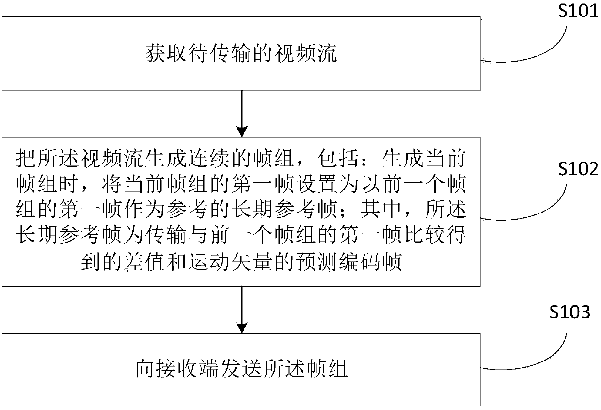
[0072] In view of the above problems, the present invention provides a video transmission method, such as figure 1 As mentioned above, it is a flow chart of the first embodiment of the video sending method of the present invention, and the video sending method includes the following steps:

[0073] Step S101: Obtain a video stream to be transmitted.

[0074] In the scenario where the user uses the network to perform real-time video communication, the video stream to be transmitted by the user is acquired.

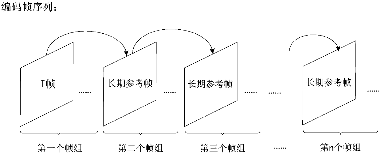
[0075] Step S102: Divide the video stream into continuous frame groups, and when generating the current frame group, set the first frame of the current frame group as a long-term reference frame for reference to the first frame of the previous frame group; wherein, the long-term The reference frame is a predictive coding frame that transmits the difference value and motion vector obtained by comparing with the first frame of the previous frame group.

[0076] Specifically...

no. 2 example

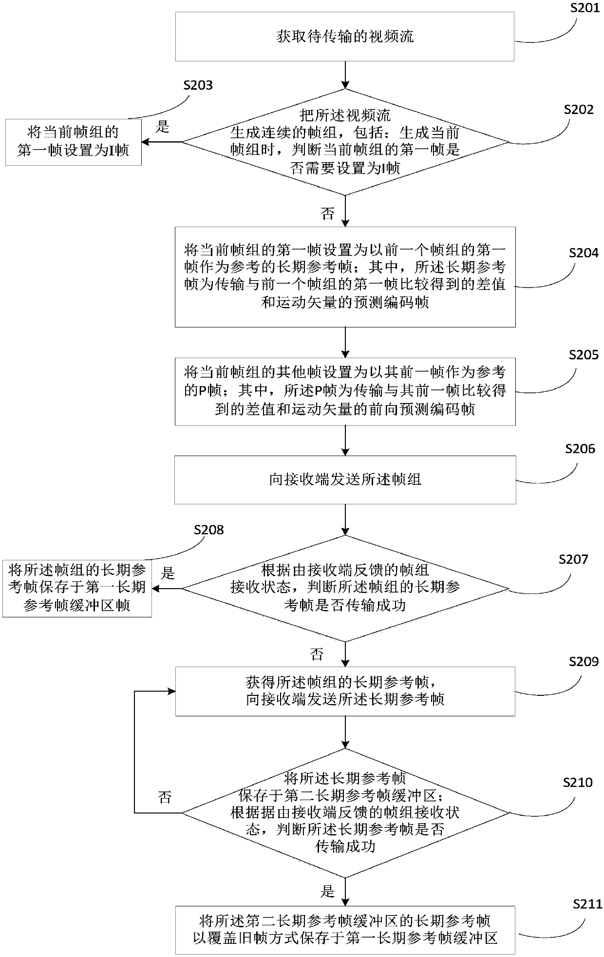
[0081] like figure 2 As mentioned above, it is a flow chart of the second embodiment of the video sending method of the present invention, and the video sending method includes the following steps:

[0082] Step S201: Obtain a video stream to be transmitted.

[0083] In the scenario where the user uses the network to perform real-time video communication, the video stream to be transmitted by the user is acquired.

[0084] Step S202: Divide the video stream into continuous frame groups; when generating the current frame group, determine whether the first frame of the current frame group needs to be set as an I frame; wherein, the I frame is an intra-frame for transmitting full-frame image information Encoded frames.

[0085] Step S203: If yes, set the first frame of the current frame group as an I frame;

[0086] Step S204: If not, set the first frame of the current frame group as the long-term reference frame for reference to the first frame of the previous frame group. ...


PUM


Abstract

The invention provides a video sending and receiving method. The video sending method comprises the following steps: acquiring a video stream to be transmitted and generating a continuous frame groupby using the video stream. The method further comprises the following steps: when a current frame group is generated, setting a first frame of the current frame group as a long-term reference frame byusing the first frame of a previous frame group as a reference, wherein the long-term reference frame is a predication coding frame for transmitting a difference value and a motion vector obtained bycomparing with the first frame of the previous frame group; and sending the frame group to the receiving end. The video receiving method comprises the following steps: receiving the frame group sentby the sending end and restoring the continuous frame group to obtain a transmitted video stream. According to the method, the defined long-term reference frame is used for replacing an original I frame in a continuous frame group of a video coding sequence when no scene is switched; the transmission time is short, the success rate is high, and the frame size of the frame group is more uniform, sothat the transmission time delay is reduced, and the probability of the packet loss situation is reduced. The invention further provides a video sending and receiving device and a terminal.

Description

technical field [0001] The present invention relates to the technical field of the Internet, in particular, the present invention relates to a video transmission method, device and terminal. Background technique [0002] With the increasing development of Internet technology, the Internet and applications combined with Internet technology have gradually become an indispensable part of people's lives. Nowadays, the applications of video transmission using the network, such as video telephony and video conferencing, are attracting more and more people's attention. However, due to the unreliability of the transmission of the Internet itself, there is a phenomenon that video frames cannot be guaranteed to be completely transmitted to the receiving end. The lack of a video frame will cause the decoding of the current and subsequent reference video frames to fail, causing the video picture to freeze. The picture cannot be restored until a video frame that can be successfully deco...

Claims


Application Information

Patent Timeline
IPC IPC(8): H04N19/44H04N19/65H04N19/172H04N19/61
CPCH04N19/172H04N19/44H04N19/61H04N19/65H04N19/105H04N19/107H04N19/109H04N19/177H04N19/423H04N19/463H04N19/58H04N19/70H04N19/176
Inventor 刘丽马跃颜乐驹刘清
Owner GUANGZHOU BAIGUOYUAN INFORMATION TECH CO LTD
Why Eureka
Try Eureka