
Voice diaphragm assembly processing method, voice diaphragm assembly and micro-loudspeaker

A processing method and sound film technology, applied in the direction of loudspeakers, sensors, electrical components, etc., can solve problems such as voice coil and sound film falling off, product failure, and reduced service life, so as to achieve uniform distribution and tight combination of sound film Effect

Active Publication Date: 2018-04-20
厦门东声电子有限公司
View PDF4 Cites 2 Cited by
  • Summary
  • Abstract
  • Description
  • Claims
  • Application Information

AI Technical Summary

Problems solved by technology

[0003] The invention aims to improve the problem that the voice coil and the sound film fall off when the speaker works for a long time, which leads to the failure of the product and the reduction of the service life.

Method used


Image

  • Voice diaphragm assembly processing method, voice diaphragm assembly and micro-loudspeaker
  • Voice diaphragm assembly processing method, voice diaphragm assembly and micro-loudspeaker
  • Voice diaphragm assembly processing method, voice diaphragm assembly and micro-loudspeaker

Examples


Embodiment 1

[0045] A processing method for a sound film component.

[0046] The sound membrane assembly includes a sound membrane and a voice coil 9 configured on the sound membrane, and the processing method includes:

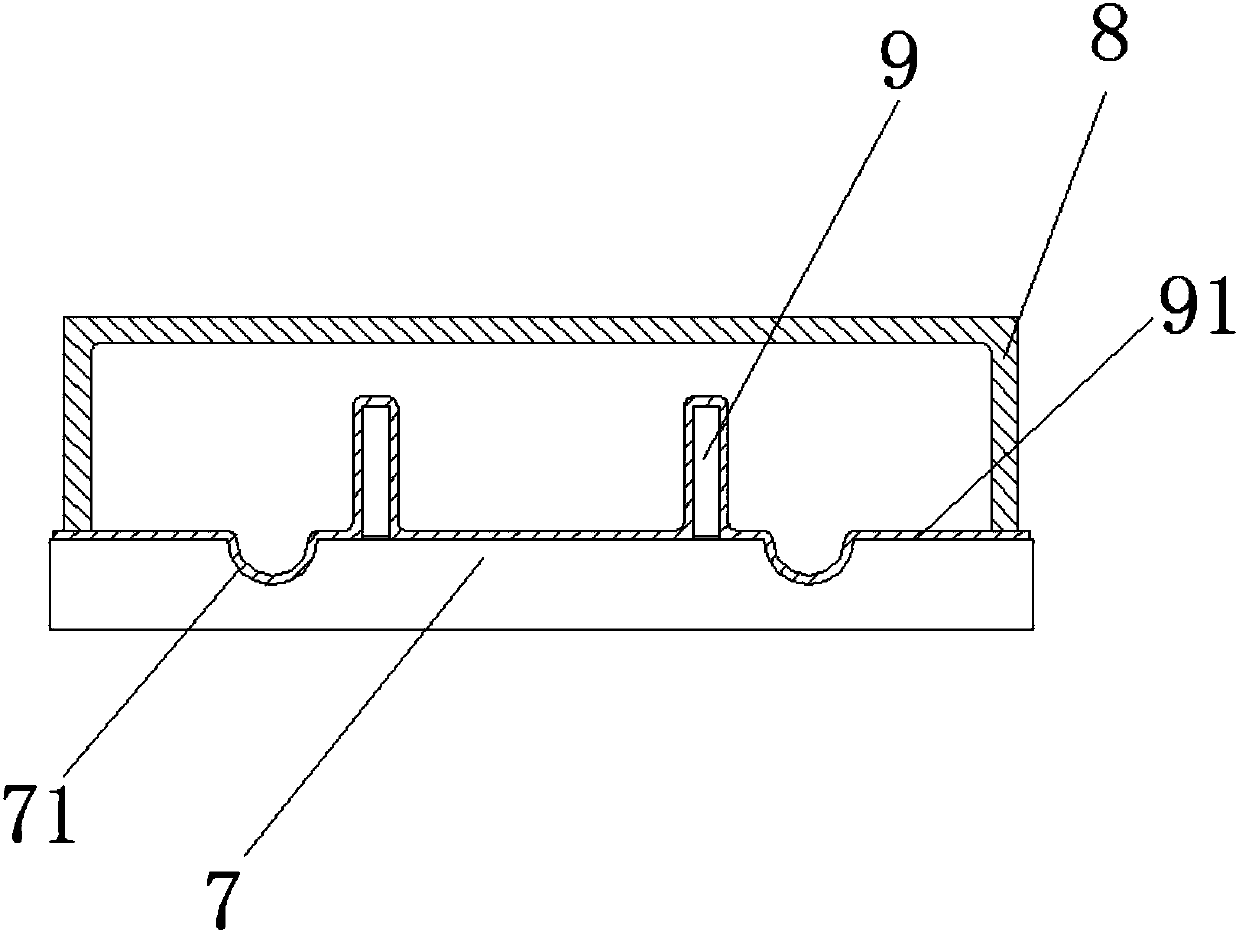
[0047] S1: Preheat the heat conduction mold to 80 degrees Celsius, and then arrange the voice coil 9 on the heat conduction mold to keep it fixed.

[0048]Among them, the preferred range of the preheating temperature of the heat conduction mold is 65 to 85 degrees Celsius, to avoid excessive heating temperature, the voice coil 9 is suddenly exposed to too high temperature and cause cracking, the preheating temperature is too low, increase the travel time, and additionally increase Time costs. In this embodiment, the preheating temperature is selected to be 80 degrees centigrade, which is moderate, and workers will not burn their hands because the temperature is too high in the next process, which is not conducive to the continuous work of workers.

[0049] S2: placing t...

Embodiment 2

[0072] The implementation principle and the technical effect of the device provided in Embodiment 2 of the present invention are the same as those of the sound membrane assembly produced by the method in Embodiment 1.

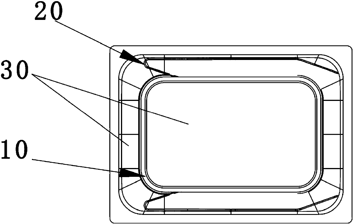
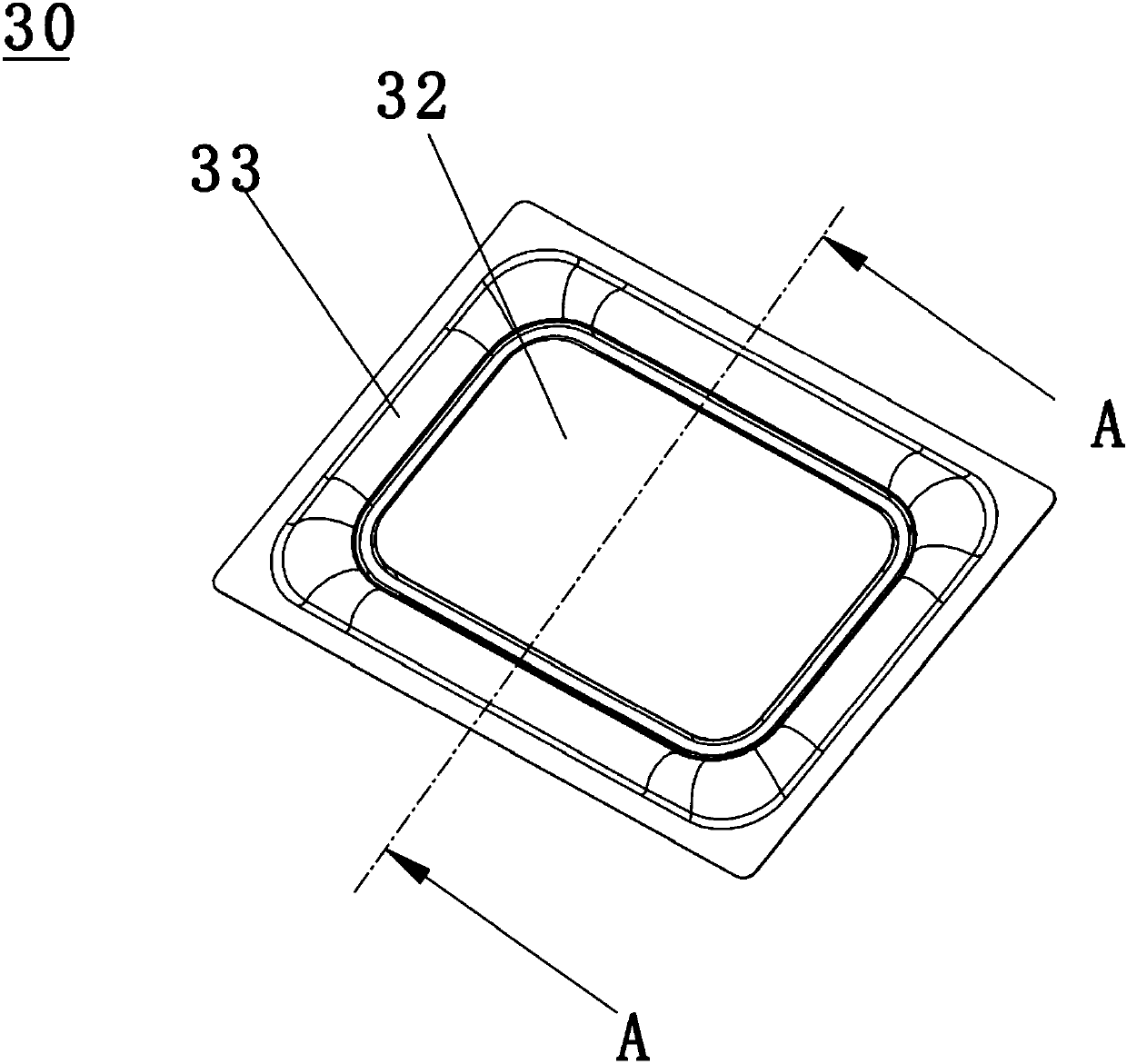
[0073] A sound membrane assembly includes a voice coil and a sound membrane 30 , the voice coil includes a coil 10 and a lead wire 20 , and the lead wire 20 is connected to the coil 10 .

[0074] The sound membrane 30 includes an annular groove portion 31, a central portion 32 and a ring portion 33; The joint with the ring portion 33 is formed by being recessed downwards.

[0075] The coil 10 is embedded in the groove of the annular groove portion 31 and connected with the annular groove portion 31 by thermoplastic.

[0076] In the acoustic membrane 30 of the present invention, the annular groove portion 31 is formed by downwardly recessing the junction of the central portion 32 and the ring portion 33 . The coil 10 is embedded in the groove of the annular gr...


PUM


Abstract

The invention provides a voice diaphragm assembly processing method, a voice diaphragm assembly and a micro-loudspeaker. The voice diaphragm assembly processing method is provided; the voice diaphragmassembly comprises a voice diaphragm and a voice coil configured on the voice diaphragm; and the processing method is characterized by comprising the steps of: configuring the voice coil on a heat conduction mould; placing a voice diaphragm sheet over the voice coil, and heating the heat conduction mould to 90-110 DEG C; applying air pressure onto the upper surface of the voice diaphragm sheet, so that the voice diaphragm sheet is completely attached onto the voice coil and the heat conduction mould, and heating the heat conduction mould to 170-180 DEG C; cooling the heat conduction mould, sothat the voice diaphragm sheet is solidified on the voice coil, and forming the voice diaphragm assembly; and separating the voice diaphragm assembly from the heat conduction mould. The voice diaphragm is firmly attached onto the voice coil in a thermoplastic manner; and thus, the voice diaphragm cannot be separated.

Description

technical field [0001] The invention relates to the field of loudspeaker manufacturing, in particular to a processing method for a sound film assembly, a sound film assembly and a micro-speaker. Background technique [0002] The vibrating membranes of existing micro-speakers are all glued to the voice coil, and the voice coil is located below the voice membrane. Because the voice coil and diaphragm are small and exquisitely bonded, they all need to be glued manually at present. Because the consistency of the glue is difficult to guarantee, the serious failure state of the coil and the sound film falling off is very likely to occur after a long time of work, which leads to the existing production method not only with low automation rate and high production cost, but also makes the product of the micro-speaker unsatisfactory. Stablize. Contents of the invention [0003] The invention aims to improve the problem that the voice coil and the sound film fall off when the louds...

Claims


Application Information

Patent Timeline
Patent Type & Authority Applications(China)
IPC IPC(8): H04R31/00H04R9/02H04R9/06
CPCH04R9/02H04R9/06H04R31/003H04R2231/001H04R2400/11
Inventor 姜鑫
Owner 厦门东声电子有限公司
Learn More