A quenching device for pulley parts

A technology for quenching devices and parts, applied in the direction of quenching devices, furnaces, heat treatment equipment, etc., can solve the problems of large limitations and parts specification restrictions, and achieve the effect of improving the scope of application

Active Publication Date: 2019-10-22
WUHAN MARINE MACHINERY PLANT
View PDF7 Cites 0 Cited by
  • Summary
  • Abstract
  • Description
  • Claims
  • Application Information

AI Technical Summary

Problems solved by technology

[0006] In order to solve the problem that the dedicated pulley quenching equipment in the prior art has large limitations and the applicable part specifications are limited, the embodiment of the present invention provides a pulley part quenching device

Method used


Image

  • A quenching device for pulley parts
  • A quenching device for pulley parts
  • A quenching device for pulley parts

Examples


Embodiment

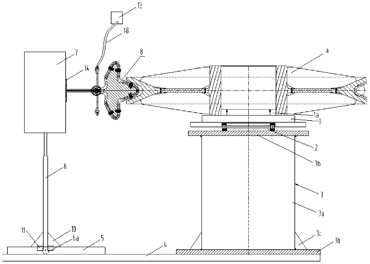
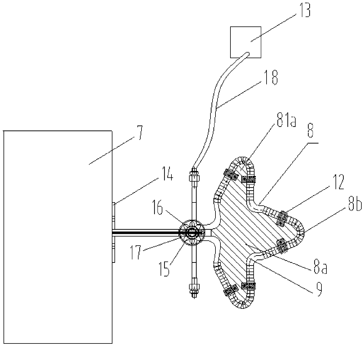
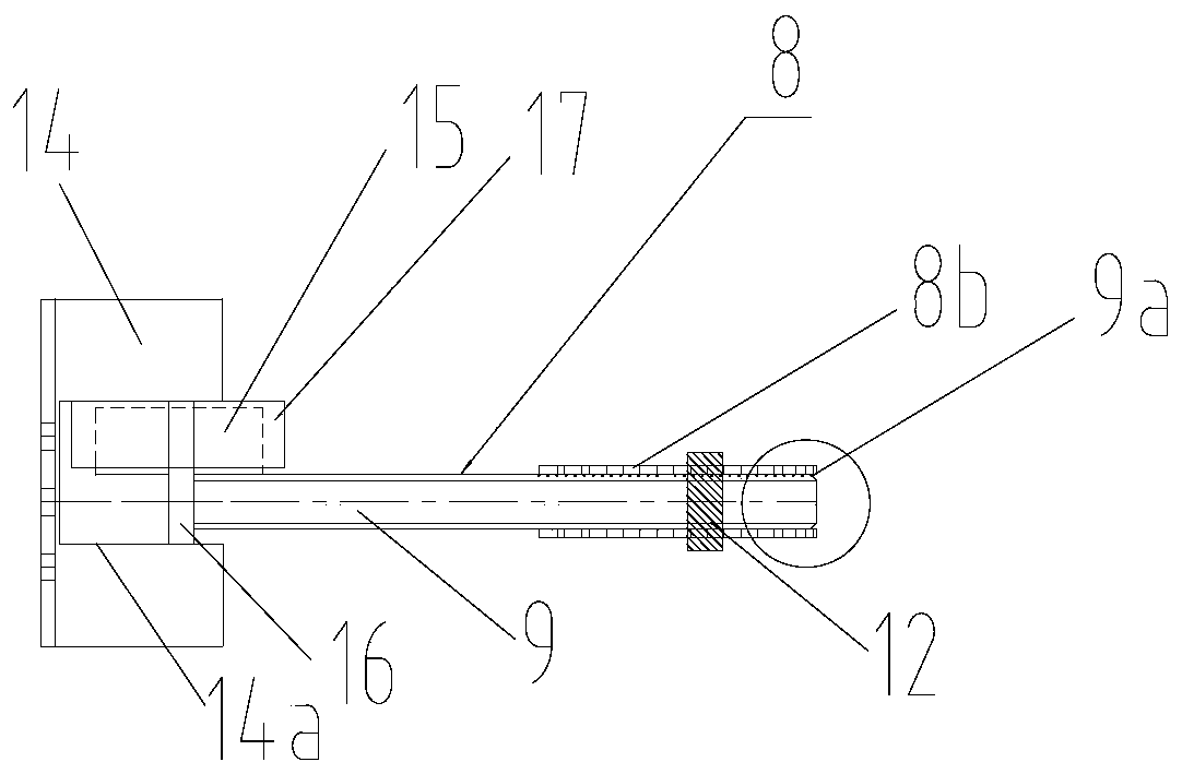
[0028] The embodiment of the present invention provides a pulley part quenching device, such as figure 1 As shown, the quenching device for pulley parts includes an inner turntable 1 , a base 3 , a bottom plate 4 , a lifting rod 6 , an electromagnetic induction heater and a mounting seat 14 . The inner turntable 1 is rotatably installed on the top of the base 3. The inner turntable 1 is used to clamp the part a to be quenched. The base 3 is fixedly installed on the bottom plate 4. One end of the lifting rod 6 is slidably arranged on the bottom plate 4. The lifting rod The sliding direction of 6 extends along the radial direction of the inner ring turntable 1. The electromagnetic induction heater includes an induction device 7 and an induction head 8 . Induction head 8 (see figure 2 ), the induction device 7 is installed on the other end of the lifting rod 6, and the induction head 8 is arranged toward the inner turntable 1. Mounting seat 14 is installed on induction device...


PUM


Abstract

The invention discloses a pulley part quenching device. The pulley part quenching device comprises an inner ring rotating disc, a base, a bottom plate, a sliding rail, a lifting rod, an electromagnetic induction heater and a mounting base; the inner ring rotating disc is rotationally arranged at the top of the base and is used for clamping parts to be quenched, and the base is fixed on the bottomplate; one end of the lifting rod is arranged in the sliding rail in a sliding mode, and the sliding direction of the lifting rod extends along the radial direction of the inner ring rotating disc; and the electromagnetic induction heater comprises induction equipment and an induction head, the induction head comprises an insulation plate, a magnetizer and a spraying pipe, and a small gear is fixed on the spraying pipe and is rotationally installed on a rotating shaft. The pulley part quenching device can adapt to the to-be-quenched parts in various sizes, so that the application range of thepulley part quenching device is enlarged.

Description

technical field [0001] The invention relates to the field of parts heat treatment, in particular to a quenching device for pulley parts. Background technique [0002] Quenching is to heat a metal workpiece to a certain temperature, and then quickly immerse it in water or oil to cool it down, thereby increasing the hardness of the metal part. [0003] At present, the rope groove quenching on the surface of pulley parts can only be carried out with special pulley quenching equipment. The special pulley quenching equipment includes the inner ring turntable, the inner ring lifting device, the outer ring heating device and the cooling liquid tank arranged at the bottom of the inner ring turntable, the inner ring turntable is arranged on the top of the inner ring lifting device, and the outer ring heating device surrounds the inner ring Turntable arrangement. The outer ring heating device can be heated by flame or electromagnetic induction, and the outer ring heating device is f...

Claims


Application Information

Patent Timeline
Patent Type & Authority Patents(China)
IPC IPC(8): C21D1/667C21D1/42C21D9/34
CPCC21D1/42C21D1/667C21D9/34Y02P10/25
Inventor 陈亮徐钢新李勃王辉
Owner WUHAN MARINE MACHINERY PLANT
Why Eureka
Try Eureka