Transmission network dynamic reconfiguration method based on 3/2 wiring mode

A technology of dynamic reconfiguration and wiring mode, applied in the direction of electrical components, circuit devices, AC network circuits, etc., can solve the problems of increasing grid investment and construction costs, reducing grid power supply reliability, and inflexible applications, so as to improve the reliability of power supply Sexuality, easy promotion and application, and simple implementation process

Active Publication Date: 2018-04-24
POWER DISPATCHING CONTROL CENT OF GUANGDONG POWER GRID CO LTD
View PDF6 Cites 7 Cited by
  • Summary
  • Abstract
  • Description
  • Claims
  • Application Information

AI Technical Summary

Problems solved by technology

[0006] The above-mentioned (1) type of grid reconfiguration method directly disentangles the electromagnetic ring network will reduce the reliability of power grid power supply. (2) type of grid reconfiguration method depends on the operation of the dispatcher and cannot be realized automatically. (3) type of transmission network Reconfiguration relies on automatic control devices, which requires increased grid investment and construction costs. Generally, a fixed construction period is required, and the application is not flexible enough

Method used


Image

  • Transmission network dynamic reconfiguration method based on 3/2 wiring mode
  • Transmission network dynamic reconfiguration method based on 3/2 wiring mode
  • Transmission network dynamic reconfiguration method based on 3/2 wiring mode

Examples


Embodiment 1

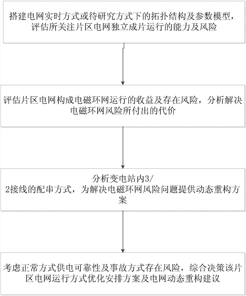
[0043] A dynamic reconfiguration method of transmission network based on 3 / 2 connection mode, such as figure 1 shown, including the following steps:

[0044] S1: Build the topological structure and parameter model of the power grid in real-time mode or in the mode to be studied, and evaluate the ability and risk of independent operation of the power grid in the concerned area;

[0045] S2: Assess the benefits and risks of the operation of the electromagnetic ring network in the power grid of the area, and analyze the price paid to solve the risk of the electromagnetic ring network;

[0046] S3: Analyze the string distribution mode of 3 / 2 wiring in the substation, and provide a dynamic reconstruction plan for solving the risk problem of the electromagnetic ring network;

[0047] S4: Considering the reliability of power supply in the normal mode and the risk of accident mode, comprehensively decide the optimal arrangement plan for the power grid operation mode in this area and ...


PUM


Abstract

The invention discloses a transmission network dynamic reconfiguration method based on a 3/2 wiring mode. The transmission network dynamic reconfiguration method comprises the steps of: constructing atopological structure and parameter model of a power grid real-time mode or a mode to be studied, and evaluating capability and risks of independent district-wide operation of district power grids ofinterest; evaluating benefits and potential risks of electromagnetic looped network operation formed by the district power grids, and analyzing a cost of solving the electromagnetic looped network risks; analyzing a 3/2 wiring string configuration method in a transformer substation, and providing a dynamic reconstruction scheme for solving the electromagnetic looped network risk problem; and considering power supply reliability of a normal mode and potential risks of an accident mode, and deciding a district power grid operation mode optimal arrangement scheme and a power grid dynamic reconfiguration suggestion comprehensively. The transmission network dynamic reconfiguration method based on the 3/2 wiring mode avoids the load flow from shifting within the electromagnetic looped network in the accident mode, does not cause overload of low-voltage level equipment or damage to the system stability, and improves the operation safety of the system.

Description

technical field [0001] The invention relates to the field of power system operation analysis and control, and more specifically, relates to a dynamic reconfiguration method of a power transmission network based on a 3 / 2 connection mode. Background technique [0002] Power grid reconfiguration refers to reorganizing the topology of the power grid by changing the on-off status of line switches / knife switches and bus tie switches to achieve network topology adjustments that meet specific operating requirements. At present, power grid reconfiguration is widely used in the distribution network, achieving the goals of balanced load distribution, improved power supply reliability, and reduced network loss. [0003] In the transmission network, the planned grid structure is usually used to maintain full wiring operation, but with the continuous strengthening of the grid structure, problems such as short-circuit current exceeding the standard and electromagnetic ring network operatio...

Claims


Application Information

Patent Timeline
Patent Type & Authority Applications(China)
IPC IPC(8): H02J3/00
CPCH02J3/00H02J2203/20
Inventor 罗钢钱峰杨银国吴国炳娄源媛易杨
Owner POWER DISPATCHING CONTROL CENT OF GUANGDONG POWER GRID CO LTD
Why Eureka
Try Eureka