Front and back anti-fog detection equipment
A technology for anti-fog and equipment, which is applied in the direction of TV, optics, instruments, etc., can solve the problems of easily generating fog and affecting the monitoring effect, and achieve the effects of preventing fog generation, improving monitoring performance, and improving adaptability
- Summary
- Abstract
- Description
- Claims
- Application Information
AI Technical Summary
Problems solved by technology
Method used
Image
Examples
Embodiment 1
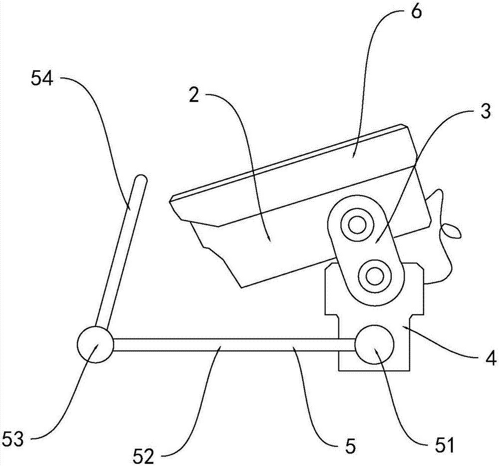
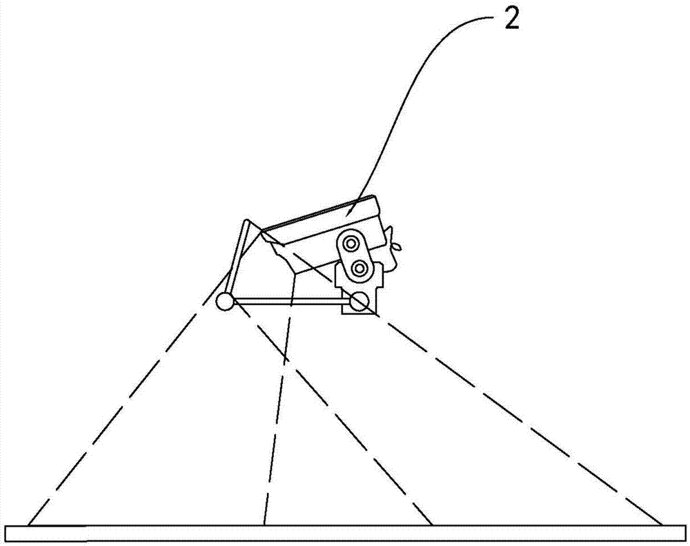
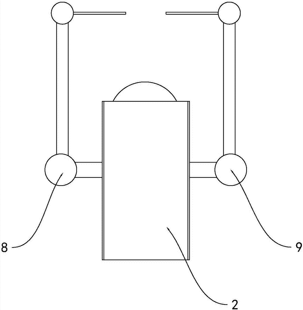
[0023] As shown in the figure, this embodiment provides a front and rear anti-fog detection device, including a camera 2, an angle adjustment shaft 3, and a support 4. The camera 2 is installed on the support 4 through the angle adjustment shaft 3, and also includes a The first reflection mechanism 8 and the second reflection mechanism 9 for expanding the monitoring range, and the anti-fog mechanism 7 for preventing fog, the first reflection mechanism 8 and the second reflection mechanism 9 are respectively installed on both sides of the camera 2, The anti-fog mechanism 7 is installed on the first reflection mechanism 8 and the second reflection mechanism 9 respectively;
[0024] The first reflection mechanism 8 and the second reflection mechanism 9 both include a primary damping shaft 51, a worm 52, a secondary damping shaft 53, and a mirror 54, and one end of the worm 52 is connected to the support 4 through the primary damping shaft 51. Connected, the reflective mirror 54 i...
Embodiment 2
[0029] This embodiment has been optimized as follows on the basis of Embodiment 1: the angle adjustment shaft 3, the primary damping shaft 51, the secondary damping shaft 53, the support 4 and the worm 52 in this embodiment are all provided with a layer of anti-corrosion coating. Floor.
[0030] The working principle of this embodiment is as follows: in the outdoor environment, various connectors are easily eroded by rainwater and rust occurs. In order to improve the service life of the equipment, this device has all the connectors provided with an anti-corrosion coating, which improves the Corrosion resistance of equipment.
Embodiment 3
[0032] The present embodiment has been optimized as follows on the basis of Embodiment 1: the top of the camera 2 of the present embodiment is also provided with a protective cover 6 for preventing rainwater invasion, and the outer contour size of the protective cover 6 is greater than the outer contour of the camera 2 size.
[0033] The working principle of this embodiment is as follows: the device is used in an outdoor environment for a long time, and pollutants such as rainwater are easy to pour into the device. After a certain amount of intrusion accumulates, it is easy to affect the heat dissipation of the equipment, resulting in overload operation of the device, which seriously affects the service life of the equipment. In response to this problem, the protective cover designed by this device can effectively prevent the intrusion of rainwater and dust, and improve the outdoor performance and service life of the equipment.
PUM
 Abstract
Description
Claims
Application Information
 - R&D
- Intellectual Property
- Life Sciences
- Materials
- Tech Scout
- Unparalleled Data Quality
- Higher Quality Content
- 60% Fewer Hallucinations
Browse by: Latest US Patents, China's latest patents, Technical Efficacy Thesaurus, Application Domain, Technology Topic, Popular Technical Reports.
© 2025 PatSnap. All rights reserved.Legal|Privacy policy|Modern Slavery Act Transparency Statement|Sitemap|About US| Contact US: help@patsnap.com


