pcsc shear force coupled structure of integrally assembled composite girder bridge with slab girder

A prefabricated and composite beam technology, which is applied in the direction of erecting/assembling bridges, bridges, bridge construction, etc., can solve problems such as difficult quality assurance, poor effectiveness of concrete bridge slabs, and inability to implement at the same time

Active Publication Date: 2019-07-23
CHONGQING JIAOTONG UNIVERSITY
View PDF8 Cites 0 Cited by
  • Summary
  • Abstract
  • Description
  • Claims
  • Application Information

AI Technical Summary

Problems solved by technology

The existing problems are: A. The weight of the concrete bridge slab is all borne by the steel beam, resulting in a large amount of steel; B. The construction period of the cast-in-place concrete is long and it is difficult to guarantee the quality; C. The prestress is applied to the bridge slab in the negative moment section, and part of the prestress is balanced by the steel beam. The effectiveness of the prestress in the concrete bridge slab is poor
Although there are a series of advantages, the fabrication and installation of the steel girder and the concrete bridge slab must be carried out successively, and cannot be carried out at the same time, which increases the construction period; there is an unfavorable working condition in the construction stage that the self-weight of the bridge slab is only borne by the steel beam Therefore, the amount of steel used has increased significantly; the welding workload on site is very large, and the welding quality is difficult to guarantee; at the same time, in order to realize prefabrication and jacking construction, the equipment for continuous and rapid prefabrication-jacking construction of bridge slab segments was also invented ( Patent application number 201611155859.5)

Method used


Image

  • pcsc shear force coupled structure of integrally assembled composite girder bridge with slab girder
  • pcsc shear force coupled structure of integrally assembled composite girder bridge with slab girder
  • pcsc shear force coupled structure of integrally assembled composite girder bridge with slab girder

Examples


Embodiment Construction

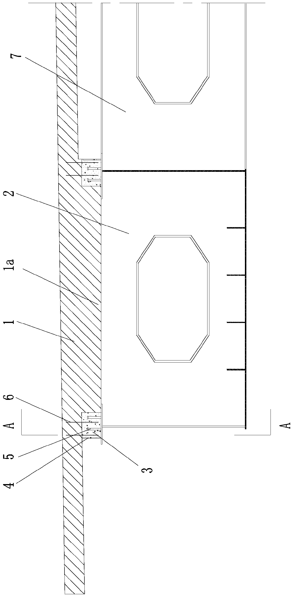
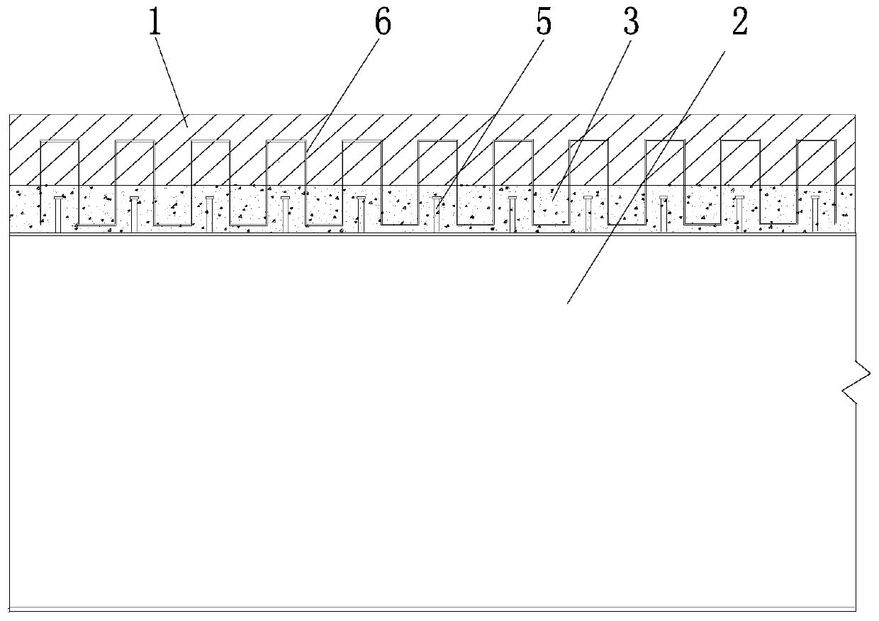
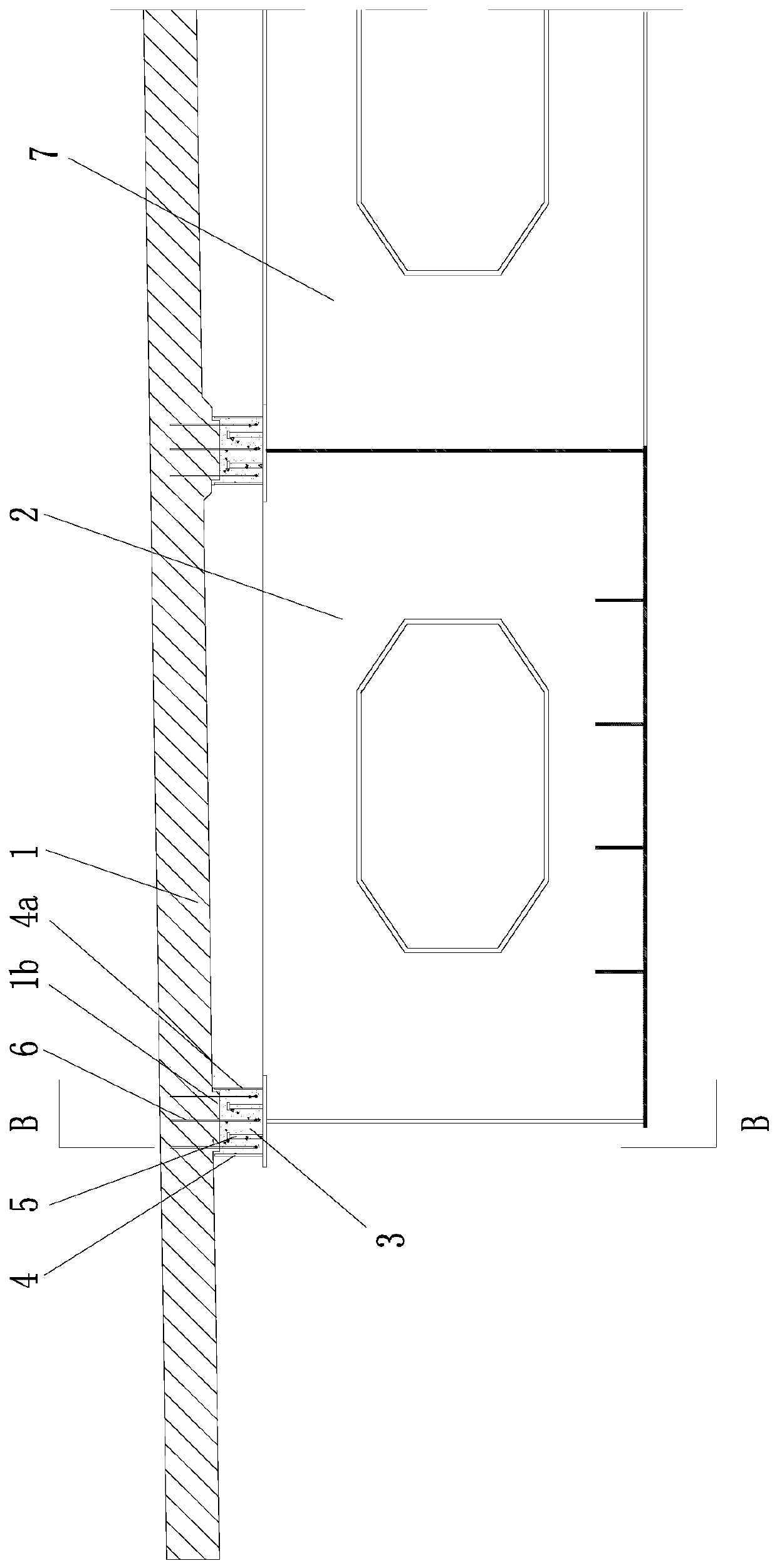
[0025] figure 1 It is a structural schematic diagram of the first embodiment of the present invention, figure 2 for figure 1 Sectional view along A-A direction; this embodiment adopts the composite girder formed by the PCSC shear connection structure of the slab girder integrally assembled composite girder bridge. Bury the shear member Ⅰ (connecting steel bar) protruding from the bottom of the slab below, set the shear member Ⅱ (shear nail) and longitudinal side baffle 4 on the top surface of the steel beam (S) along the longitudinal direction, install the bridge deck on the steel beam Put it in place, make the pre-embedded connecting steel bars of the bridge slab embedded in the longitudinal side baffle 4 on the top surface of the steel beam, and then close the long strip-shaped closed cavity formed by the top surface of the steel beam, the two side baffles and the top surface of the bridge slab. Perform pressure pouring combined with concrete (C) to form a PCSC shear conn...


PUM


Abstract

The invention discloses a PCSC shear joint structure of a plate girder overall assembly type composite beam bridge. A steel beam is provided with a longitudinal side baffle. A precast concrete bridgechannel plate is located behind the steel beam and is located on the top of the longitudinal side baffle. A longitudinal perfusion space is formed between the precast concrete bridge channel plate andthe steel beam. The precast concrete bridge channel plate is fixedly connected with the steel beam by using a shear joint structure in a longitudinal perfusion mode between the precast concrete bridge channel plate and the steel beam. According to the PCSC shear joint structure of the plate girder overall assembly type composite beam bridge, by using pressure perfusion, a longitudinal perfusion space is formed and the longitudinal perfusion space is combined with concrete to form steel-concrete composite beams, and then all the steel-concrete composite beams are pushed to the corresponding bridge piers to be in position in the longitudinal direction, and assembly type combination of an overall precast concrete bridge channel plate unit and an overall steel beam unit is achieved. An assembly type industrialization bridge construction method that the steel-concrete composite beams are constructed in a factory and the fact that all the steel-concrete composite beams are pushed to the corresponding bridge piers to be in position in the longitudinal direction can be achieved. All the advantages of the PCSC shear joint structure are achieved. The three problems of the high working amount of welding on a site, extremely high accuracy requirements of adaptation of manufacture and poor fatigue resistance of inconel weld are overcome.

Description

technical field [0001] The invention belongs to the field of building structures and bridge engineering, and in particular relates to a PCSC shear force coupling structure of a plate girder integrally assembled composite girder bridge. Background technique [0002] The steel-concrete composite structure has obvious advantages in terms of material strength, convenient and fast construction, reliable structural performance, and recyclability, so it has become more and more the development trend of bridge structures; due to the steel structure and concrete bridge slab material Therefore, how to connect the two easily and quickly with long-term reliable performance is a problem that the engineering community has been exploring and solving. [0003] In the existing steel-concrete composite girder bridges, steel girders with shear nails on the top surface are usually erected first. There are two construction methods for concrete bridge slabs. One is to form a concrete bridge slab ...

Claims


Application Information

Patent Timeline
Patent Type & Authority Patents(China)
IPC IPC(8): E01D21/00
CPCE01D21/00E01D2101/268
Inventor 周志祥周劲宇乔心格
Owner CHONGQING JIAOTONG UNIVERSITY
Why Eureka
Try Eureka