Support structure and electronic device

A support structure and support rod technology, which is applied in the direction of lighting devices, machines/brackets, lighting auxiliary devices, etc., can solve problems such as insufficient clamping force at joints, and achieve the effects of eliminating potential safety hazards, facilitating positioning, and preventing potential safety hazards

Active Publication Date: 2018-04-27
吴江科技创业园管理服务有限公司
View PDF5 Cites 3 Cited by
  • Summary
  • Abstract
  • Description
  • Claims
  • Application Information

AI Technical Summary

Problems solved by technology

[0004] The purpose of the present invention is to provide a bracket structure and an electronic device, which can solve the safety problem encountered in the prior art due to insufficient clamping force at the joint

Method used


Image

  • Support structure and electronic device
  • Support structure and electronic device
  • Support structure and electronic device

Examples


Embodiment Construction

[0042] In order to have a further understanding of the purpose, structure, features, and functions of the present invention, the following detailed descriptions are provided in conjunction with the embodiments.

[0043] Certain terms are used in the description and claims to refer to particular elements. Those of ordinary skill in the art will appreciate that manufacturers may refer to the same element by different terms. The specification and claims do not use the difference in name as a way to distinguish components, but use the difference in function of components as a criterion for distinguishing. "Include" mentioned throughout the specification and claims is an open term, so it should be interpreted as "including but not limited to".

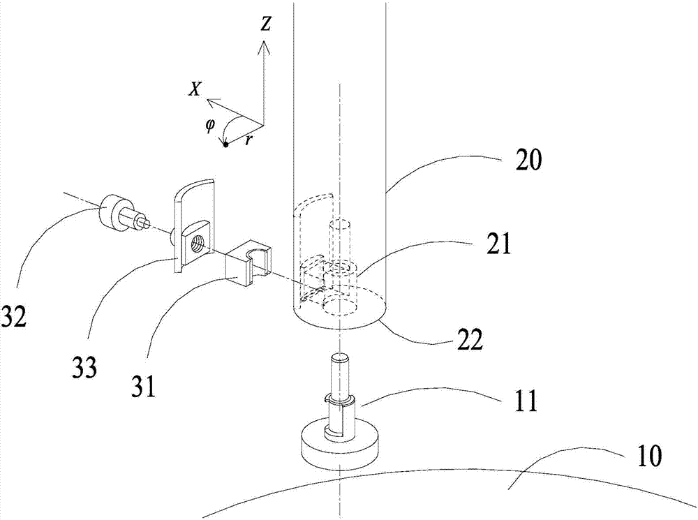
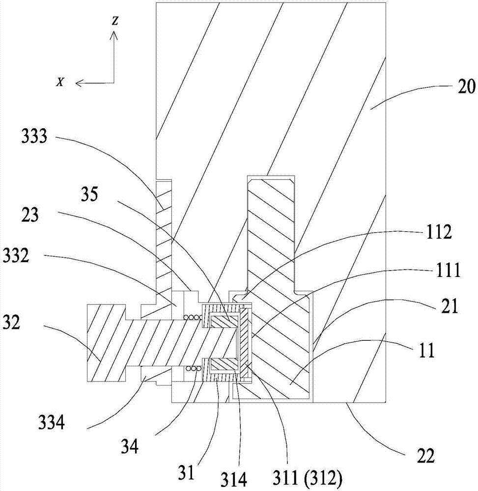
[0044] refer to Figure 2A to Figure 3C Shown is a schematic structural view of the first embodiment of the stent structure of the present invention.

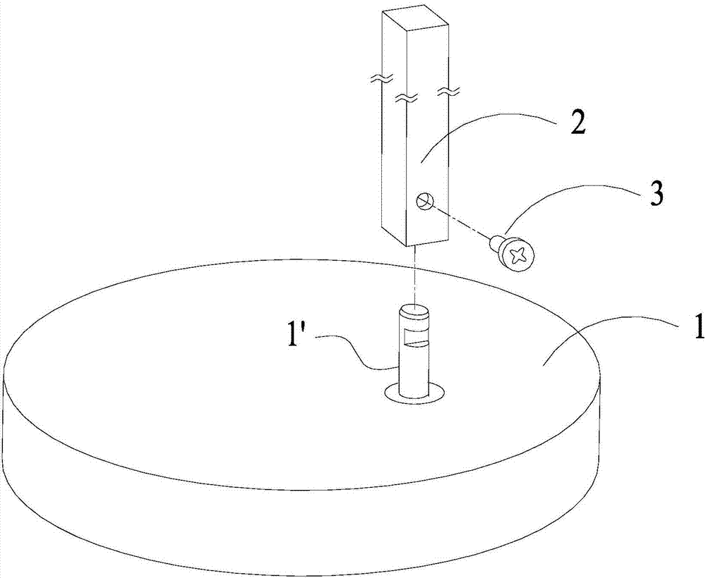
[0045] The support structure includes a base 10, a support rod 20 and a fastening ass...


PUM


Abstract

The invention provides a support structure and an electronic device adopting the same. The support structure comprises a base, a support rod and a fastening assembly, wherein the base is inserted intoone end surface of the support rod through a bulgy bottom post, and the support rod is rotationally connected to the base by the fastening assembly; the bottom post comprises a first cambered surfacepart, a first blocking part, a second blocking part and a third blocking part, the first cambered surface part can be propped against the fastening assembly and rotate relative to the fastening assembly, the first blocking part prevents the fastening assembly from separating from the top side, and the second blocking part and the third blocking part limit the rotating angle of the fastening assembly relative to the bottom post. By means of the propped joint and relative damping rotation of the fastening assembly and the first cambered surface part, adjustment and maintaining of the relative position between the support rod and the base is realized, the movement range of a second cambered surface part is limited by the first blocking part, the second blocking part and the third blocking part in different directions, so that existing potential safety hazards are eliminated, and a user performs rapid positioning conveniently according to use conditions.

Description

technical field [0001] The invention relates to a bracket structure and an electronic device using the bracket structure, in particular to a rotatable bracket structure. Background technique [0002] Prior art stent structure, see figure 1 . One end of a rod-shaped support rod 2 (such as a lamp arm) is inserted into the protrusion 1' in the base 1, and then locked and abutted against the protrusion by a screw 3 to achieve fixation. Since the screws and protrusions are usually made of hard metal materials, the friction between the two is limited, and the joints in the bracket structure are prone to fall off, causing the rod-shaped support rod to fall or the base to fall. In addition, the rod-shaped support rod cannot rotate relative to the base, which limits the scope of use of the device using the support structure. [0003] Therefore, it is necessary to design a novel stent structure to overcome the above defects. Contents of the invention [0004] The purpose of the ...

Claims


Application Information

Patent Timeline
Patent Type & Authority Applications(China)
IPC IPC(8): F16M11/06F16M11/16F21V21/084
CPCF16M11/06F16M11/16F21V21/084
Inventor 施云瀚
Owner 吴江科技创业园管理服务有限公司
Why Eureka
Try Eureka