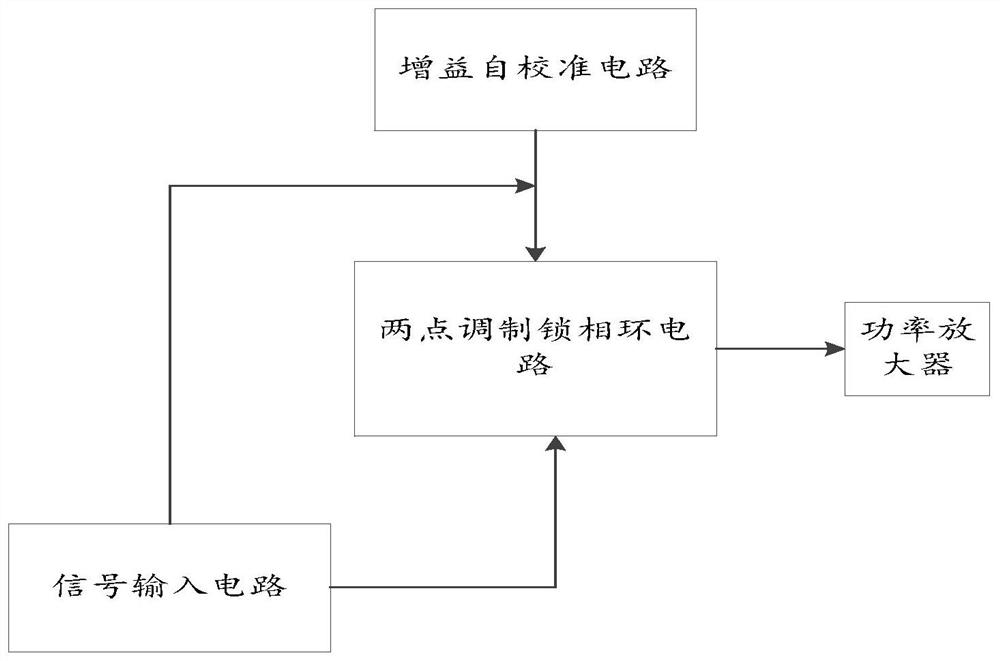
A two-point modulation transmitter calibration circuit and calibration method
A technology for calibrating circuits and transmitters, applied in the field of transmitters, can solve the problems of low-pass branch, high-pass branch delay and poor gain matching, etc.
- Summary
- Abstract
- Description
- Claims
- Application Information
AI Technical Summary
Problems solved by technology
Method used
Image
Examples
specific Embodiment
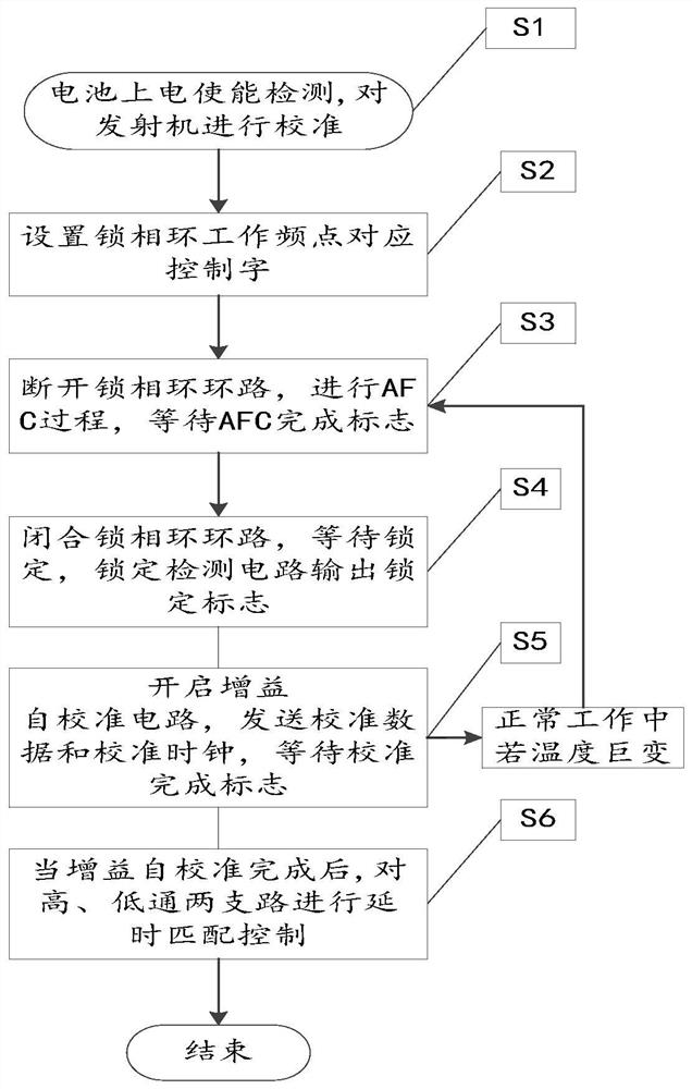
[0058] Step Ⅰ: Battery power-on enable detection. After power-on is detected, the transmitter should be ready to transmit. Before signal communication, the transmitter needs to be calibrated to ensure communication quality.
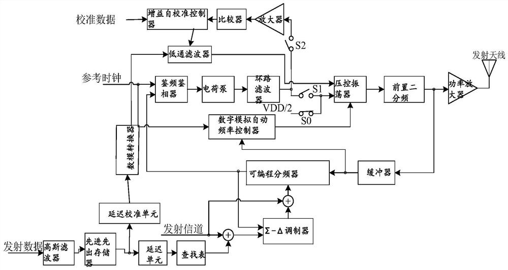
[0059] Step Ⅱ: If figure 1 As shown, set the integer frequency division ratio and fractional frequency division ratio control word corresponding to the operating frequency of the phase-locked loop through the RF Channel, and enable the module of the open-loop path of the phase-locked loop.
[0060] Step Ⅲ: If figure 1 As shown, closing S0 and opening S1 cuts off the PLL loop, and at the same time opens S2 to carry out the automatic frequency control (AFC) process. At this time, the loop is formed by VCO, Pre-Divider 2, Buffer, and Digital / Analog AFC The circuit realizes the rough adjustment of the working frequency of the phase-locked loop, so that the phase-locked loop is locked within a certain error range of the working frequency point, and waits fo...
PUM
 Abstract
Description
Claims
Application Information
 - R&D
- Intellectual Property
- Life Sciences
- Materials
- Tech Scout
- Unparalleled Data Quality
- Higher Quality Content
- 60% Fewer Hallucinations
Browse by: Latest US Patents, China's latest patents, Technical Efficacy Thesaurus, Application Domain, Technology Topic, Popular Technical Reports.
© 2025 PatSnap. All rights reserved.Legal|Privacy policy|Modern Slavery Act Transparency Statement|Sitemap|About US| Contact US: help@patsnap.com


