Structure of valve sleeve turning fixture

A valve body and fixture technology, which is applied in the direction of clamping, manufacturing tools, supports, etc., can solve the problems of inconvenient clamping process, complex clamping structure, and low positioning accuracy, so as to simplify the clamping process, improve processing quality, and install clip structure simple effect

Active Publication Date: 2018-05-04
MEISHAN CRRC BRAKE SCI & TECH CO LTD
View PDF15 Cites 1 Cited by
  • Summary
  • Abstract
  • Description
  • Claims
  • Application Information

AI Technical Summary

Problems solved by technology

[0002] For the turning processing of a certain valve body cover, one end of the valve body structure is a straight port, and the other end is a protruding part, and the protruding part is not allowed to bear force, so the clamping process of the valve body cover processing is very difficult. It is inconvenient, and the clamping structure is complicated, and the positioning accuracy is not high, which affects the processing quality of the valve body

Method used


Image

  • Structure of valve sleeve turning fixture
  • Structure of valve sleeve turning fixture

Examples


Embodiment Construction

[0012] Below in conjunction with accompanying drawing, the present invention is described in detail.

[0013] In order to make the object, technical solution and advantages of the present invention clearer, the present invention will be further described in detail below in conjunction with the accompanying drawings and embodiments. It should be understood that the specific embodiments described here are only used to explain the present invention, not to limit the present invention.

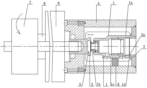
[0014] like figure 1 As shown, a valve body holster fixture structure, one end of the valve body 1 is a straight port structure 1a, the other end is provided with a protruding part 1b, the lower side is a plane 1c, the protruding part is not allowed to bear force, so The fixture structure includes a positioning sleeve 2 arranged at one end of the straight mouth structure 1a of the valve body 1, a clamping head 3 arranged at one end of the protruding part 1b of the valve body 1, and a clamping dri...


PUM


Abstract

The invention discloses a structure of a valve sleeve turning fixture. The structure comprises a positioning sleeve, a clamping head and a clamping drive mechanism, wherein one end of the positioningsleeve is fixedly connected onto a clamp body, a bulge part is arranged axially at the other end of the positioning sleeve, the bulge part of the positioning sleeve is correspondingly matched with a step part of the end surface of a straight-port structure of the valve body, and a groove is formed in the end surface of a clamping head; when the valve body is clamped, the bulge part of the valve body is located in the groove, and the stress point of the clamping head for clamping the valve body is positioned on the valve body end surface on the periphery of the bulge part. According to structural design of the positioning sleeve and the clamping head which are located at two ends of the valve body, effective positioning is formed by the positioning sleeve and a straight port of the valve body, the groove in the end surface of the clamping head is used for preventing the bulge part at the end of the valve body from being damaged by clamping, two ends of the valve body are directly clamped by the positioning sleeve and the clamping head, and the clamping process is greatly simplified; moreover, the clamping structure is simple, positioning accuracy is high, and valve sleeve turning quality is effectively improved.

Description

technical field [0001] The invention belongs to the technical field of railway vehicle parts processing, and in particular relates to a clamp structure for a valve body cover. Background technique [0002] For the turning processing of a certain valve body cover, one end of the valve body structure is a straight port, and the other end is a protruding part, and the protruding part is not allowed to bear force, so the clamping process of the valve body cover processing is very difficult. Inconvenient, and the clamping structure is complicated, and the positioning accuracy is not high, which affects the processing quality of the valve body. Contents of the invention [0003] The purpose of the present invention is to provide a valve body cover clamp structure with simple structure, high positioning accuracy and convenient clamping process in view of the above existing problems. [0004] The technical solution of the present invention is realized in the following way: a clam...

Claims


Application Information

Patent Timeline
Patent Type & Authority Applications(China)
IPC IPC(8): B23Q3/12
CPCB23Q3/12
Inventor 邵向兰黄群力毛富英张凤玲余越川
Owner MEISHAN CRRC BRAKE SCI & TECH CO LTD
Why Eureka
Try Eureka