A feeding mechanism for a composite machine

A compounding machine and feeding technology, applied in thin material processing, lamination auxiliary operations, chemical instruments and methods, etc., can solve the problems of reducing the yield, affecting the compounding effect, dislocation of the surface of the cloth, etc., to reduce the degree of deflection, Improve stability and avoid loosening effect

Active Publication Date: 2020-08-14
浙江恒祥新材料股份有限公司
View PDF7 Cites 0 Cited by
  • Summary
  • Abstract
  • Description
  • Claims
  • Application Information

AI Technical Summary

Problems solved by technology

However, when loading materials, due to various influencing factors are uncertain, such as the unbalanced roll breaking of the feeding rack, the deflection of the cloth during the transmission process, etc., it is easy to cause misalignment and wrinkles on the surface of the cloth, which will affect the subsequent compounding effect and reduce the Yield

Method used


Image

  • A feeding mechanism for a composite machine
  • A feeding mechanism for a composite machine
  • A feeding mechanism for a composite machine

Examples


Embodiment Construction

[0034] The present invention will be described in detail below in conjunction with the accompanying drawings and embodiments.

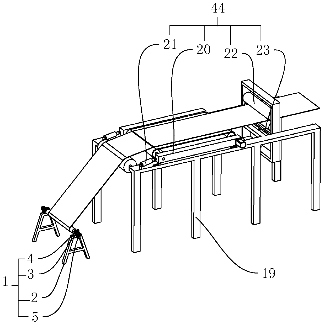
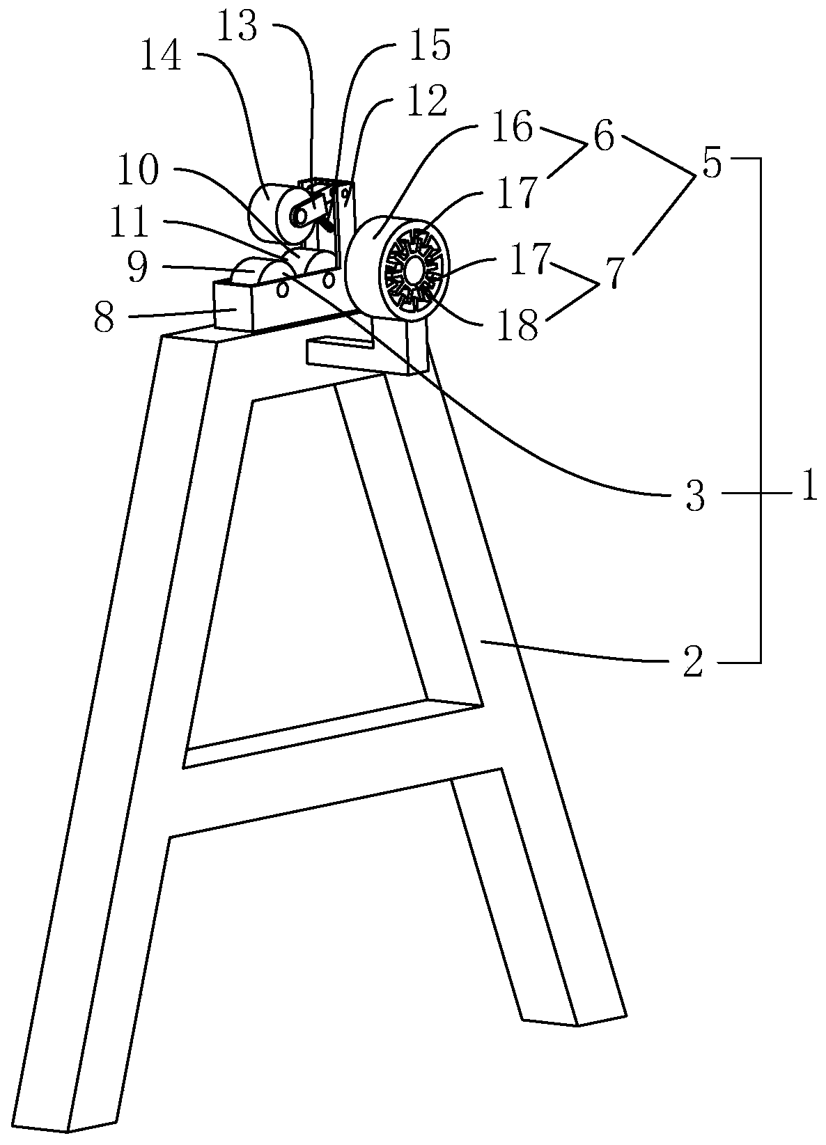
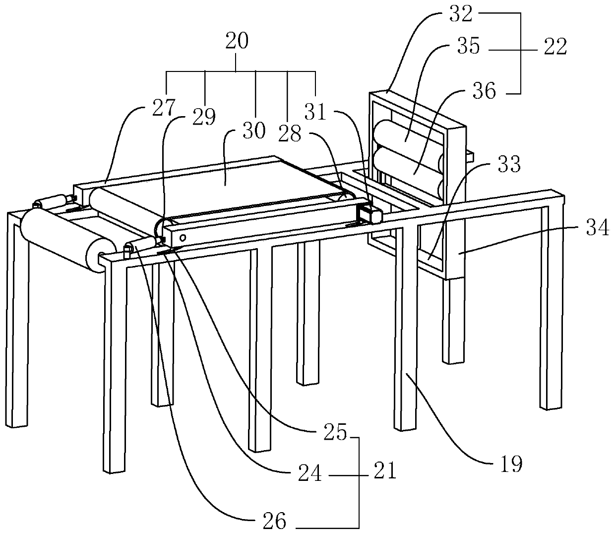
[0035] A feeding mechanism of a composite machine, such as figure 1 As shown, it includes a feeding device 1, the feeding device 1 includes a frame 2 placed on the ground, a support mechanism 3 is provided on the top of the frame 2, and the support mechanism 3 is equipped with a feeding rod 4 for sheathing a cloth roll. The two ends of the feeding rod 4 are built on the support mechanism 3 and can rotate freely. A brake mechanism 5 is arranged between the frame 2 and the feeding rod 4. The force end of the brake mechanism 5 acts on the two ends of the feeding rod 4. The brake mechanism 5 increases the resistance when the feeding rod 4 rotates, thereby effectively preventing the excessive rotation of the feeding rod 4 under the action of inertia; Higher than the feeding device 1, the cloth broken by the feeding device 1 is sent to the cloth guide fram...


PUM


Abstract

The invention discloses a feeding mechanism of a combining machine and aims to solve the problem that a conventional compounding machine is poor in cloth flatness when cloth is fed. According to the technical scheme, the feeding mechanism of the combining machine comprises a feeding device, wherein a cloth guide rack is arranged behind the feeding device; the feeding device comprises a rack; a support mechanism is arranged at the top of the rack; a feeding rod which is sleeved by a cloth roll is erected on the support mechanism; a brake mechanism is arranged between the rack and the feeding rod; and a deviation correction device is arranged at the top end of the cloth guide rack. By adopting the feeding mechanism of the combining machine, the flatness of cloth can be improved, deviation ofthe cloth in the conveying process is reduced, and the combining effect is improved.

Description

technical field [0001] The invention relates to the field of cloth composite equipment, more specifically, it relates to a feeding mechanism of a composite machine. Background technique [0002] When producing a sofa with a composite structure, it is necessary to combine two layers of fabrics of different materials through glue. Usually, a composite machine is used. The single-layer fabric is rolled up in the form of a cloth roll. When the fabric is sent to the composite machine for composite processing , firstly, the cloth roll needs to be placed on the loading rack, and then the cloth roll is pulled and broken by the cloth guide device, and the cloth is transported to the compounding place of the compound machine for glue compounding. However, when loading materials, due to various influencing factors are uncertain, such as the unbalanced roll breaking of the feeding rack, the deflection of the cloth during the transmission process, etc., it is easy to cause misalignment a...

Claims


Application Information

Patent Timeline
Patent Type & Authority Patents(China)
IPC IPC(8): B32B38/18B65H20/00
CPCB32B38/1833B65H20/00
Inventor 金国明
Owner 浙江恒祥新材料股份有限公司
Why Eureka
Try Eureka