Road surface tramper

A technology of road pavement and tamping device, which is applied in the fields of soil protection, construction, infrastructure engineering, etc. It can solve the problems of affecting the service life of the machine, wasting manpower, and poor effect, so as to improve tamping efficiency, reduce operation steps, and improve The effect of automatic control rate

Inactive Publication Date: 2018-05-04
吴琼
View PDF0 Cites 7 Cited by
  • Summary
  • Abstract
  • Description
  • Claims
  • Application Information

AI Technical Summary

Problems solved by technology

[0002] During the construction of municipal roads, the foundation of the road needs to be leveled and compacted to prevent the road surface from sinking and deforming under heavy pressure in the future. At this stage, the compaction of the road surface is mainly completed by road rollers. However, due to the large size of road rollers, for some roadside Locations, especially roadside locations where there are protective devices, cannot use road rollers to complete the compaction of the road surface. For these locations, other methods are required for compaction. The traditional method of manual compaction is not only ineffective, but also Moreover, it is a waste of manpower, which has been abandoned now. At this stage, small-scale compaction machines are used more often. However, the traditional small-scale compaction machines have inconsistencies in the leveling of the road surface, which easily leads to the disadvantage of uneven height. Moreover, the traditional compaction machine structure Complex, and its transmission mechanism is easily damaged due to long-term large alternating stress, which directly affects the service life of the machine

Method used


Image

  • Road surface tramper
  • Road surface tramper
  • Road surface tramper

Examples


Embodiment Construction

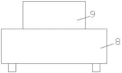
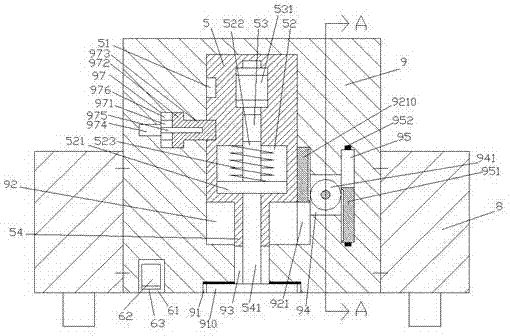
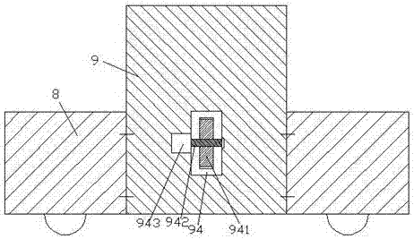
[0018] Such as Figure 1-Figure 4 As shown, a road surface tamper of the present invention includes a device body 8 and a tamping body 9 fixedly installed in the device body 8, and a first sliding cavity 92 is provided in the tamping body 9, A groove 91 is provided in the bottom end surface of the tamping body 9 directly below the first sliding chamber 92, and a sliding hole 93 is formed between the top of the groove 91 and the bottom of the first sliding chamber 92. A tamping block mechanism 5 is slidably connected to the first sliding cavity 92, and a firm locking mechanism 97 is provided on the left inner wall of the first sliding cavity 92 for locking and fitting connection with the tamping block mechanism 5. The stable locking mechanism 97 includes a locking sliding chamber 971 and a locking sliding block 973 that is slidingly fitted and connected in the locking sliding chamber 971. The inner walls of the upper and lower sides of the left section of the locking sliding ch...


PUM


Abstract

The invention discloses a road surface tramper. The road surface tramper comprises a device car body, and a tramper body fixedly mounted in the device car body; a first slide cavity is formed in the tramper body; a groove is formed in the bottom end surface of the tramper body rightly below the first slide cavity; a slide hole is inserted between the top of the groove and the bottom of the first slide cavity; a tramping block mechanism is slidingly matched and connected into the first slide cavity; a stable locking mechanism in locking cooperation connection with the tramping block mechanism is arranged in the inner wall of the left side of the first slide cavity; the stable locking mechanism comprises a locking slide cavity, and a locking slide block slidingly matched and connected into the locking slide cavity; first guide grooves are symmetrically arranged on the inner walls of the upper and lower sides of the left side section of the locking slide cavity; the first guide grooves onthe upper and lower sides are slidingly matched and connected with guide blocks; and the inner sides of the guide blocks on the upper and lower sides are fixedly connected with the outer walls of theupper and lower sides of the locking slide block. The road surface tramper is simple in structure and convenient to operate, reduces operation steps, improves the tramping efficiency, reduces the tramping construction cost, and meanwhile, prolongs the service life.

Description

technical field [0001] The invention relates to the technical field of road construction, in particular to a road surface compactor. Background technique [0002] During the construction of municipal roads, the foundation of the road needs to be leveled and compacted to prevent the road surface from sinking and deforming under heavy pressure in the future. At this stage, the compaction of the road surface is mainly completed by road rollers. However, due to the large size of road rollers, for some roadside Locations, especially roadside locations where there are protective devices, cannot use road rollers to complete the compaction of the road surface. For these locations, other methods are required for compaction. The traditional method of manual compaction is not only ineffective, but also Moreover, it is a waste of manpower, which has been abandoned now. At this stage, small-scale compaction machines are used more often. However, the traditional small-scale compaction mac...

Claims


Application Information

Patent Timeline
Patent Type & Authority Applications(China)
IPC IPC(8): E02D3/046
CPCE02D3/046
Inventor 吴琼
Owner 吴琼
Why Eureka
Try Eureka