Vehicle-mounted fertilizing device

The technology of a fertilization device and a fertilizer applicator is applied in the directions of a fertilizer applicator, a fertilizer applicator with a centrifugal wheel, a fertilizer distributor, etc., which can solve the problems of high labor intensity, low fertilizer application efficiency, poor fertilizer application effect, etc., so as to improve work efficiency and improve The effect of automatic control rate and convenient operation

Inactive Publication Date: 2017-12-22
范春苏
View PDF4 Cites 1 Cited by
  • Summary
  • Abstract
  • Description
  • Claims
  • Application Information

AI Technical Summary

Problems solved by technology

[0002] China is a large agricultural country. With the development of modern agricultural science and technology, scientific and reasonable fertilization is the basic guarantee for maintaining sufficient and balanced water and soil nutrients, crop growth and stable yield, especially for large-scale farmland, but for It is still a cumbersome processing procedure for large-scale crops, and the artificial fertilization is not uniform enough, which leads to waste of fertilizers, and also affects the absorption of fertilizers by crops. The existing agricultural fertilization devices have low fertilization efficiency and low fertilization effect. Poor, high labor intensity, complex structure of fertilization device, inconvenient operation, time-consuming and laborious to use, poor fertilization effect, increased workload of operators, unable to meet the needs of rapid fertilization of existing crops, greatly Reduced performance of fertilization unit

Method used


Image

  • Vehicle-mounted fertilizing device
  • Vehicle-mounted fertilizing device
  • Vehicle-mounted fertilizing device

Examples


Embodiment Construction

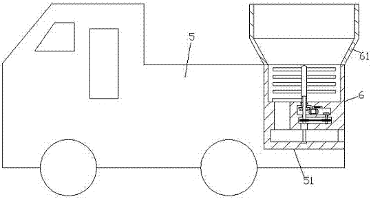
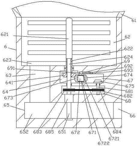
[0018] Such as Figure 1-Figure 4 As shown, a vehicle-mounted fertilization device of the present invention includes a mobile vehicle 5 and a fertilizer applicator 6, the top end of the right side of the mobile vehicle 5 is provided with an installation groove 51, and the fertilizer applicator 6 is installed in the installation groove 51 and Fixed connection, the top of the fertilizer applicator 6 is provided with a feed hopper 61, the wall of the fertilizer applicator 6 below the bottom of the feed hopper 61 is provided with a stirring chamber 62, and the inner bottom wall on the left side of the stirring chamber 62 is provided with The discharge port 63 extending downwards, the bottom extension end of the discharge port 63 is connected to the centrifugal fertilization chamber 65 extending to the right, and the fertilizer 6 wall below the middle position of the stirring chamber 62 A first transmission chamber 64 is provided, and a rotating sleeve 622 extending up and down is ...


PUM


Abstract

The invention discloses a vehicle-mounted fertilizing device. The vehicle-mounted fertilizing device comprises a moving vehicle and a fertilizing unit, wherein a mounting groove is formed in the tail end of the top of the right side of the moving vehicle; the fertilizing unit is mounted inside the mounting groove and is fixedly connected with the mounting groove; a feed hopper is arranged at the top of the fertilizing unit; a stirring cavity is formed in a fertilizing unit wall body below the bottom of the feed hopper; a discharge port stretching downwardly is formed in the inner bottom wall of the left side of the stirring cavity; a centrifugal fertilizing cavity stretching rightwards is formed in the stretching tail end of the bottom of the discharge port in a communicated manner; a first transmission cavity is formed in a fertilizing unit wall body below the middle position of the stirring cavity; a rotating sleeve stretching up and down is rotationally connected into a fertilizing unit wall body between the first transmission cavity and the stirring cavity in a matched manner; and the stretching tail end of the top of the rotating sleeve stretches into the stirring cavity, and a baffle plate is fixedly arranged on the outer surface of the left side of the rotating sleeve stretching into the stirring cavity. The vehicle-mounted fertilizing device is simple in structure and convenient to operate; during using, the vehicle-mounted fertilizing device saves time and labor, improves the fertilizing effect and reduces the workload of an operator; and the using performance of the fertilizing device is greatly improved.

Description

technical field [0001] The invention relates to the field of fertilization machinery, in particular to a vehicle-mounted fertilization device. Background technique [0002] China is a large agricultural country. With the development of modern agricultural science and technology, scientific and reasonable fertilization is the basic guarantee for maintaining sufficient and balanced water and soil nutrients, crop growth and stable yield, especially for large-scale farmland, but for It is still a cumbersome processing procedure for large-scale crops, and the artificial fertilization is not uniform enough, which leads to waste of fertilizer and also affects the absorption of fertilizer by crops. The existing agricultural fertilization devices have low fertilization efficiency and low fertilization effect. Poor, high labor intensity, complex structure of fertilization device, inconvenient operation, time-consuming and laborious to use, poor fertilization effect, increased workload...

Claims


Application Information

Patent Timeline
Patent Type & Authority Applications(China)
IPC IPC(8): A01C17/00A01C15/00
CPCA01C15/007A01C17/001A01C17/005A01C17/008Y02P60/21
Inventor 范春苏
Owner 范春苏
Why Eureka
Try Eureka