Multi-phase fluid sampling method and apparatus

a multi-phase fluid and sampling method technology, applied in the direction of instruments, withdrawing sample devices, material analysis, etc., can solve the problems of significant difficulties in obtaining truly representative samples, inability to accurately measure the density of the stream, and inability to obtain truly representative samples, etc., to achieve accurate and economical accurate and economical, and reliable and accurate multi-phase fluid flow measurement

Active Publication Date: 2006-06-29
SAUDI ARABIAN OIL CO
View PDF6 Cites 27 Cited by
  • Summary
  • Abstract
  • Description
  • Claims
  • Application Information

AI Technical Summary

Benefits of technology

[0022] Yet another object of the invention is to provide an improved apparatus and method employing foaming agents in wet gas metering applications that is more accurate and economical than known techniques.
[0023] It is another object of the invention to provide an apparatus and method that can be used in place of prior art two-and three-phase test separators to obtain reliable and accurate multi-phase fluid flow measurements and for the reliable recovery of representative fluid samples from the flowing fluid stream.
[0024] Another object of the invention is to provide an apparatus and methods for sa

Problems solved by technology

However, for the purposes of obtaining an accurate analysis of the content of the fluid stream, such as for certifying its BTU value in a custody transfer context, or determining what downstream treatments may be required for removing undesired water vapor and/or certain types of vaporized hydrocarbons in a process stream feeding a reactor, current analytical methods and apparatus are found to be lacking.
As is well known in the art, significant difficulties are associated with obtaining truly representative samples of the fluid from pressurized pipelines and in providing the sample in a state that is analyzable by any of the number of known standard techniques.
These limitations represent a serious problem to the industry, since there are approximately 1.5 million natural gas wells worldwide, many of which produce a multi-phase fluid flow of natural gas, hydrocarbon liquids and water, called “wet gas”.
Furthermore, when the fluid stream is sampled, additional condensation can occur due to the temperature and pressure differences between the mixture in the pipeline and in the sampling apparatus.
Since the condensed components of the gas are commonly the heavy ends that are also rich in BTU content, these condensed components may never be analyzed because they cling to the walls of the equipment or drip back into the pipeline.
Thus, the sample that is obtained where these conditions are prevalent is biased “lean”, with the result that the BTU content of the gas flow in the pipeline is actually greater than that of the non-representative sample.
Mathematical models have been proposed, but none have been found that reliably predicts the flow regime of three-phase flowing fluids.
Currently, the petroleum industry has no suitable technology for extracting samples of a natural gas containing any form of liquid that is proportional to the liquid load of the source gas.
Liquid aerosols, which are the most frequen

Method used


Image

  • Multi-phase fluid sampling method and apparatus
  • Multi-phase fluid sampling method and apparatus
  • Multi-phase fluid sampling method and apparatus

Examples


Embodiment Construction

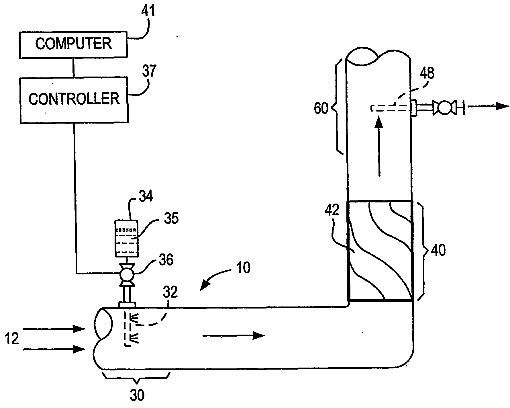
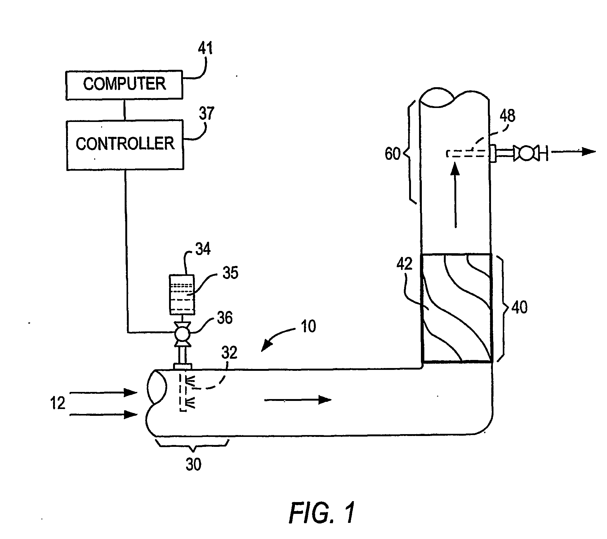
[0067] Referring to FIG. 1, there is shown a portion of a gas transmission pipeline 10 that has been provided with one embodiment of the apparatus 20 of the invention. A surfactant injection zone 30 includes one or more liquid surfactant injection jets, quills or nozzles 32 in fluid communication with surfactant storage containers 34 and metering pumps 36. The amount of surfactant 35 to be added to the fluid stream 12 is determined based on a number of parameters, including the operating pressure and temperature of the fluid, the type and approximate amount of hydrocarbon liquids and water present.

[0068] The metering pumps 36 can be manually activated. In a preferred embodiment, a controller 37 directed by a programmed general purpose computer 41 actuates the flow of surfactant through the nozzles 32. These variables will be generally known to the operator of the pipeline and one of ordinary skill in the art will be able to determine the type and rate of addition of the one or more...


PUM


Abstract

The invention provides a method for producing a homogenous sample of a pressurized fluid stream flowing in a pipeline, the fluid stream consisting of a majority component of hydrocarbon gas, the remainder consisting of one or more hydrocarbon liquids and water in the form of vapor, aerosols, droplets and/or liquid streams, the method includes the steps of: a. injecting one or more surface active agents into the fluid stream in an injection zone at a rate that is sufficient to form a uniform foam of the gas and the one or more hydrocarbon liquids and water components; b. mixing the one or more surface active agents with the fluid stream in a mixing zone to form a uniform foam composition flowing in the pipeline downstream of the mixing zone; c. withdrawing a portion of the foam composition from the pipeline at a sampling point; d. passing the portion of the foam composition withdrawn through a sampling loop; and e. removing a sample of predetermined volume of the foam composition from the sampling loop for analysis.

Description

FIELD OF THE INVENTION [0001] This invention relates to methods and apparatus for sampling a multi-phase fluid stream that includes hydrocarbon gas as the major component, and hydrocarbon liquid(s) and water in a minor proportion, the samples being used for analysis and reporting of the content of the stream, e.g., for custody transfer accounting purposes in a gas transmission pipeline, well production applications, including gas-liquid separation facilities, and various types of meters, including venturi and differential pressure (“DP”) flow meters, wet gas meters, gas turbine and ultrasonic meters. BACKGROUND OF THE INVENTION [0002] Natural gas conveyed through gas transmission pipelines is typically accompanied by minor proportions of water vapor and one or more vaporized liquid hydrocarbons. While these minor proportions of the later components are liquids at ambient pressure and temperature, the prevailing conditions in the pipeline will keep these compounds in a vaporized stat...

Claims


Application Information

Patent Timeline
IPC IPC(8): G01N1/10B01JG01N1/00G01N1/20G01N1/22G01N33/28
CPCG01N1/2035G01N33/28G01N2001/105Y10T436/25875Y10T436/2575Y10T436/21Y10T436/216Y10T436/214Y10T436/212Y10T436/218
Inventor HASSELL, JAMES CLYDE JR.
Owner SAUDI ARABIAN OIL CO
Why Eureka
Try Eureka