
Portable hydrodynamic cavitation manifold

a manifold and hydrodynamic technology, applied in the field of fluid handling, can solve the problems of inability to economically support mixers, cavities and bubbles to collapse, and ineffective use of static mixers with many high viscosity fluids, and achieve high mixing efficiency, high flow rate, and predictable pressure loss

Active Publication Date: 2011-12-15
BRISBEN WATER SOLUTIONS
View PDF3 Cites 27 Cited by
  • Summary
  • Abstract
  • Description
  • Claims
  • Application Information

AI Technical Summary

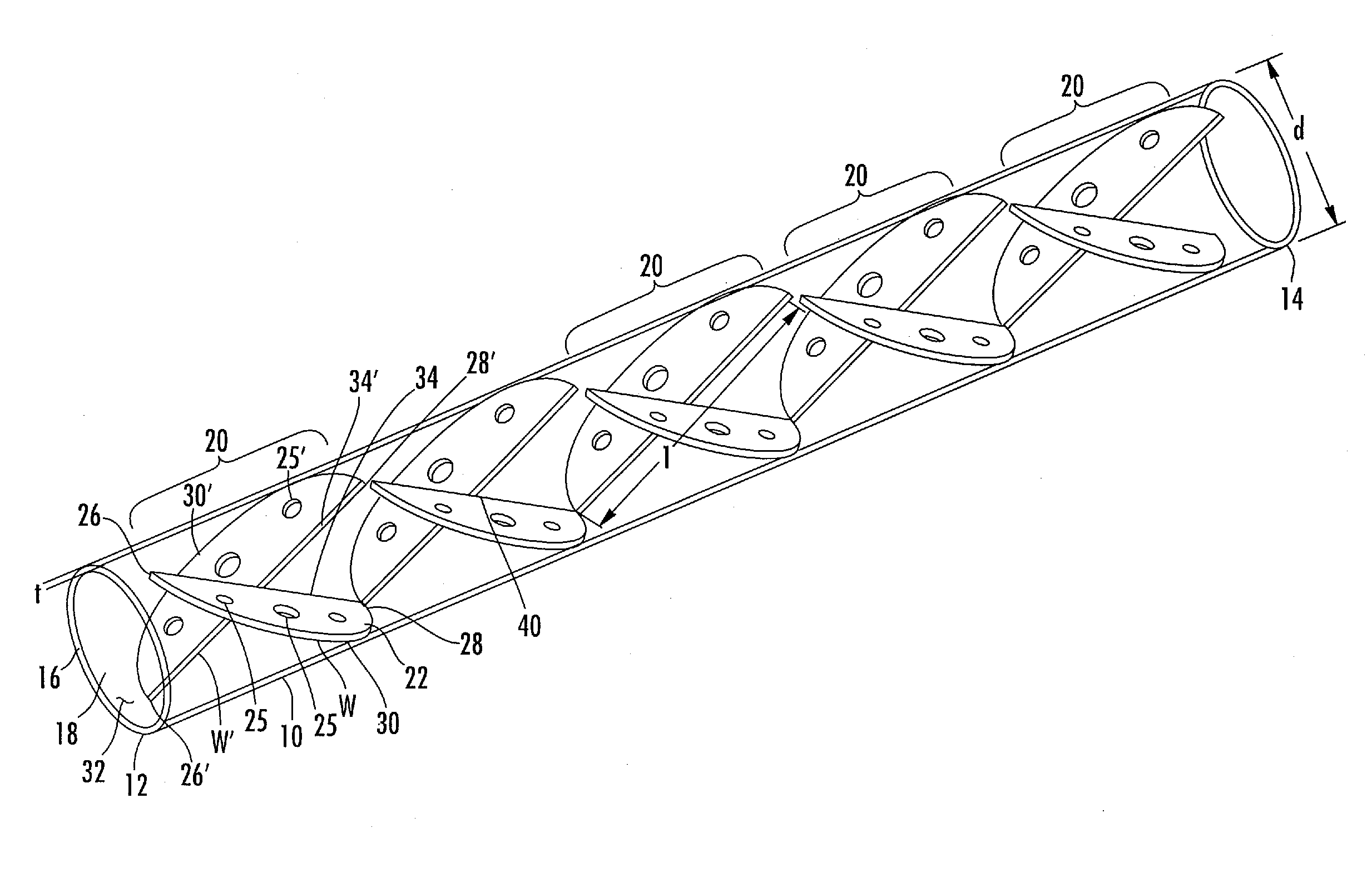
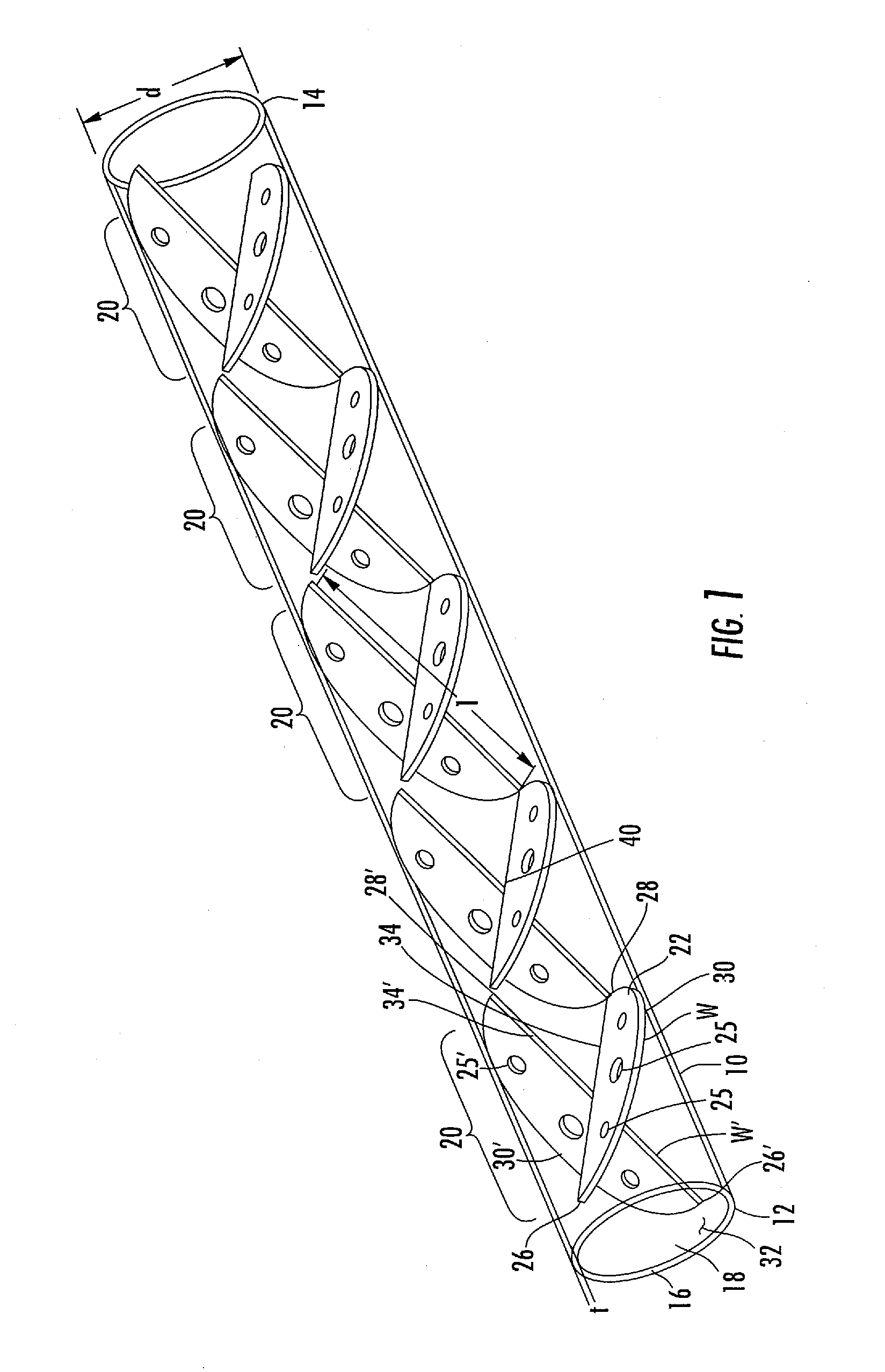
Benefits of technology

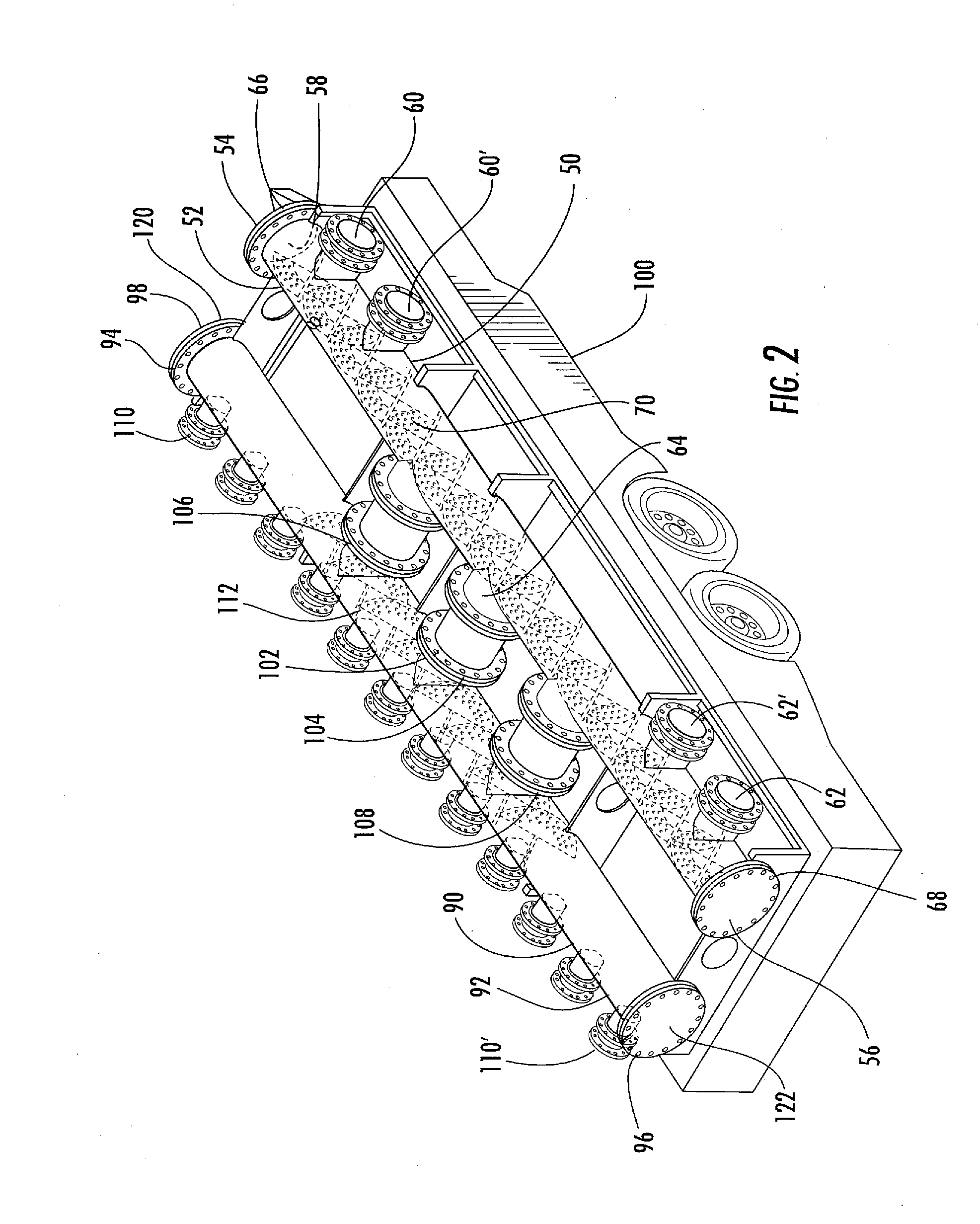
[0011]It is another objective of the instant invention to provide a portable hydrodynamic cavitation device which can operate at high mixing efficiencies and allow for receipt from multiple sources and deliver to multiple Frac tank systems.
[0012]It is an another objective of the instant invention to provide a hydrodynamic cavitation manifold having internal baffles positioned along alternating 45 degree angled plates allowing higher flow rates with predictable pressure losses.
[0013]It is yet another objective of the instant invention to provide a hydrodynamic cavitation device having angular positioning of baffles to provide for continuous flushing of suspended solids to prevent clogging.

Problems solved by technology

While this type of mixer has achieved commercial success for mixing, use of a static mixer is ineffective with many high viscosity fluids.
In addition, such mixers would be economically unfeasible in situations wherein a high flow rate and rapid mixing is required.
Where these bubbles and cavities enter a zone having increased pressure, vapor condensation takes place within the cavities and bubbles, almost instantaneously, causing the cavities and bubbles to collapse, creating very large pressure impulses.
The magnitude of the pressure impulses within the collapsing cavities and bubbles may reach ultra high pressures implosions leading to the formation of shock waves that emanate from the point of each collapsed bubble.
The phenomenon consists in the formation of hollow spaces which are filled with a vapor gas mixture in the interior of a fast-flowing liquid flow or at peripheral regions of a fixed body which is difficult for the fluid to flow around and the result is a local pressure drop caused by the liquid movement.
At a particular velocity the pressure may fall below the vapor pressure of the liquid being pumped, thus causing partial vaporization of the cavitating fluid.

Method used


Image

  • Portable hydrodynamic cavitation manifold
  • Portable hydrodynamic cavitation manifold
  • Portable hydrodynamic cavitation manifold

Examples


Embodiment Construction

[0019]In many gas fields, gas is trapped in shale formations that require stimulating the well using a process known as fracturing or fracing. The fracing process uses large amounts of water and large amounts of particulate fracing material (frac sands) to enable extraction of the gas from the shale formations. After the well site has been stimulated the water pumped into the well during the fracing process is removed. The water removed from the well is referred to as flowback fluid or frac water. A typical fracing process uses millions of gallons of water to fracture the formations of a single well. Recycling of frac water has the benefit of reducing waste product, namely the flowback fluid, which will need to be properly disposed. On site processing equipment, at the well, is the most cost effective and environmentally friendly way of recycling this natural resource.

[0020]A horizontal well takes approximately 4.5 million gallons of fresh water for the fracture process. This water ...


PUM


Abstract

A portable hydrodynamic cavitation manifold assembly formed from cylindrical tubes having flow-through chambers for collection and distribution of fluids. Each chamber includes a series of baffle units each unit formed from a first plate defined by a first end spaced apart from a second end by a length. The first plate includes a curved outer edge sized to follow the inner side wall of the chamber and a straight inner edge extending from the first end to the second end along the approximate center line of the chamber and positioned at a 45 degree angle relative to the longitudinal length of the tube. A second plate, forming a mirror image of the first plate, is also positioned at a 45 degree angle relative to the longitudinal length of the tube and at a 90 degree angle to the first plate. Each plate includes a plurality of apertures sized to control the velocity of the fluid flow, each aperture having edge walls to induce constriction for hydrodynamic cavitation mixing of fluids.

Description

PRIORITY CLAIM[0001]This application is a continuation-in-part of U.S. patent application Ser. No. 12 / 816,014, filed Jun. 15, 2010, the contents of which are incorporated herein by reference.FIELD OF THE INVENTION[0002]This invention relates to fluid handling and, more particularly, to a portable hydrodynamic manifold for use in providing a uniform fluid mixture at a Frac site.BACKGROUND OF THE INVENTION[0003]In-line fluid flow static mixers are known in the art and generally consist of mixing baffles arranged so that when a material is discharged from one baffle, it discharges with a swirling action and strikes the downstream baffle. The fluid flow divides before it passes on to the next succeeding baffle, which again divides the flow into various streams. While this type of mixer has achieved commercial success for mixing, use of a static mixer is ineffective with many high viscosity fluids. U.S. Pat. Nos. 4,511,258 and 4,936,689 disclose static mixer having a sinuous cross-sectio...

Claims


Application Information

Patent Timeline
Patent Type & Authority Applications(United States)
IPC IPC(8): B01F5/06
CPCB01F5/0619B01F25/43161
Inventor MCGUIRE, DENNISJAKHETE, SANJEEV
Owner BRISBEN WATER SOLUTIONS
Learn More