Mixer for gas engine and exhaust gas recirculation (EGR) mixer

A gas engine and mixer technology, which is applied to engine components, machines/engines, mechanical equipment, etc., can solve the problems that the mixing uniformity of recirculated exhaust gas and fresh air can no longer meet the requirements of engine stable operation, and the intake pipeline is short. , to achieve good market application value, low overall cost, and high gas utilization efficiency

Active Publication Date: 2017-05-31
成都耐尔特科技有限公司
View PDF7 Cites 26 Cited by
  • Summary
  • Abstract
  • Description
  • Claims
  • Application Information

AI Technical Summary

Problems solved by technology

Now with the improvement and maturity of EGR technology, the amount of recirculated exhaust gas (EGR rate) is increasing, and the requirement of engine compactness makes the intake pipeline shorter, so the ratio of recirculated exhaust gas and fresh air obtained by traditional methods Mixing uniformity can no longer meet the requirements of stable engine operation

Method used


Image

  • Mixer for gas engine and exhaust gas recirculation (EGR) mixer
  • Mixer for gas engine and exhaust gas recirculation (EGR) mixer
  • Mixer for gas engine and exhaust gas recirculation (EGR) mixer

Examples


Embodiment 1

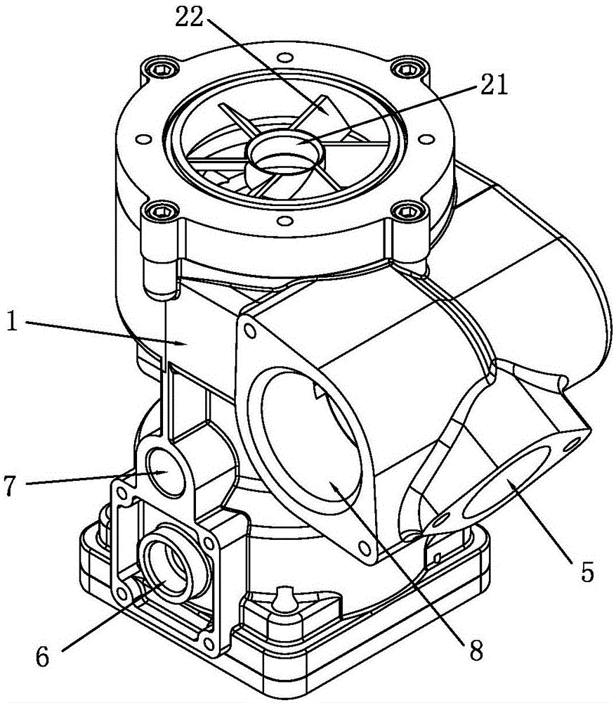
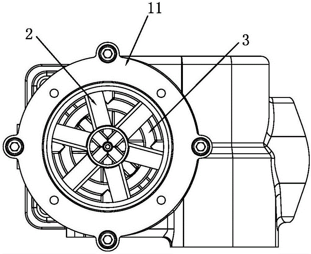
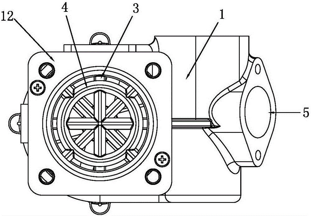
[0030] Such as figure 1 with Figure 5 As shown, a gas engine mixer provided by this embodiment includes a mixer body 1 that penetrates up and down. The upper end of the mixer body 1 is an air inlet, and the lower end is an air outlet. There is a turbulent body 2, a gas core 4 is provided at the gas outlet, an EGR core 3 is provided between the turbulent body 2 and the gas core 4, and the mixer body 1 is provided with an exhaust gas inlet 5 and a gas inlet 6 , the EGR core 3 communicates with the exhaust gas inlet 5, and the EGR core is used to inject the exhaust gas connected to the exhaust gas inlet into the mixer body. The gas wick 4 communicates with the gas inlet 6, and the gas wick is used for injecting the gas connected to the gas inlet into the mixer body. The EGR core 3 and the gas core 4 have the same structure, and the following will further describe the EGR core 3 and the gas core 4 by taking the gas core as an example.

[0031] Such as Figure 5 with Image 6...

Embodiment 2

[0056] Such as Figure 8 with Figure 9 As shown, another gas engine mixer provided in this embodiment differs from the gas engine mixer in Embodiment 1 only in that the gas core 4 is arranged at the air inlet of the mixer body 1, The turbulent body 2 is arranged at the gas outlet of the mixer body 1 , and the EGR core 3 is arranged between the gas core 4 and the turbulent body 2 . The EGR core 3 communicates with the exhaust gas inlet 5, the gas core 4 communicates with the gas inlet 6, and the positions of the exhaust gas inlet 5 and the gas inlet 6 are adjusted according to the positions of the EGR core 3 and the gas core 4 Make adaptive changes.

Embodiment 3

[0058] Such as Figure 10 with Figure 11 As shown, an EGR mixer provided in this embodiment includes a mixer body 1, an EGR core 3 and a turbulent body 2 are arranged in the mixer body 1 along the flow direction of the air, and an exhaust gas is arranged on the mixer body 1. The intake port 5 and the exhaust gas intake port 5 communicate with the EGR core 3 .

[0059] The EGR core 3 in this embodiment has the same structure as the gas core in Embodiment 1, including a guide ring, a guide column arranged in the guide ring, and a guide ring arranged between the guide ring and the inner wall of the mixer. Ventilation column, diversion column, guide ring and ventilation column are all provided with spray holes; the diversion column intersects at the center of the guide ring and divides the guide ring into four uniform parts, and the ventilation column divides the guide ring And the space between the mixer body is divided into four uniform parts. The cross-sections of the guide...


PUM


Abstract

The invention discloses a mixer for a gas engine and an exhaust gas recirculation (EGR) mixer. The mixer for the gas engine comprises a through mixer body. A turbulent flow body is arranged at an air inlet of the mixer body. A gas core is arranged at an air outlet of the mixer body. An EGR core is arranged between the turbulent flow body and the gas core. An exhaust gas inlet and a gas inlet are formed in the mixer body. The EGR core communicates with the exhaust gas inlet. The gas core communicates with the gas inlet. The mixer for the gas engine is suitable for various kinds of gas engines, the mixing efficiency is high, operation of the engine is more stable, and the utilization efficiency of gas is higher. Requirements for periphery conditions are lower than those of independent gas mixers and EGR mixers, the total cost is lower, safety and reliability are achieved, the sealing performance is good, and the mixer for the gas engine and the EGR mixer have great market application value.

Description

technical field [0001] The invention belongs to the technical field of gas engine gas systems, and in particular relates to a mixer for a gas engine and an EGR mixer. Background technique [0002] Exhaust Gas Recirculation (EGR for short) refers to the technology that the internal combustion engine separates a part of the exhaust gas after combustion and introduces it into the intake side to make it burn again. The main purpose is to reduce the nitrogen oxides in the exhaust gas (NOx) and partial load sharing can improve fuel consumption. The oxygen content in the exhaust gas after combustion of the internal combustion engine is extremely low or even non-existent. After the exhaust gas is mixed with the inhalation air, the oxygen concentration in the inhalation air will be reduced, so the following phenomena will occur: the oxygen content lower than the atmosphere is burning When the temperature is lowered, the generation of nitrogen oxides (NOx) will be suppressed. When t...

Claims


Application Information

Patent Timeline
Patent Type & Authority Applications(China)
IPC IPC(8): F02M26/19
CPCY02T10/30
Inventor 陈友荣陈元滨陈勇
Owner 成都耐尔特科技有限公司
Why Eureka
Try Eureka