Optical wave electric water heater and inner container assembly thereof

A technology for electric water heaters and tanks, applied in the field of light wave electric water heaters and their tank components, can solve the problems of inability to separate water and electricity, leakage of electricity, etc., and achieve the effect of improving safety and eliminating leakage of electricity

Pending Publication Date: 2018-05-04
合肥万和电气有限公司
0 Cites 0 Cited by

AI-Extracted Technical Summary

Problems solved by technology

However, the development of traditional electric water heater technology has encountered bottlenecks this year, the most notable of which is its safety
[0003] Bathing safety has always been the focus of consumer...

Method used

Further, the liner assembly 10 also includes a reflective heat insulating medium 80, which is wrapped around the end of the light wave tube body 42 close to the open end of the sleeve 30, so that the light wave tube body 42 faces the sleeve 30 The light waves radiated from the opening end are reflected by the light-reflecting and heat-insulating medium 80, which avoids direct radiation heating of the connection between the opening end of the casing 30 and the connecting pipe 20, and reduces the friction between the sealing ring 90, the sealant 50 and the opening end of the casing 30. The thermal expansion makes the sealing performance more stable and further improves the safety of the light wave electric water heater.
Further, the liner assembly 10 also includes an elastic member 60 arranged in the sleeve 30, one end of the light wave tube body 42 abuts against the sealant 50, and the other end abuts against the elastic member 60, and the elastic member 60 is far away from the light wave One end of the tube body 42 abuts against the closed end of the sleeve 30 to provide a pre-tightening force for the optical wave tube body 42 to move along the sleeve toward the connecting tube 20 . In this way, it is convenient to locate and fix the light wave tube main body 42 at the center of the sleeve 30 , and has the effect of anti-vibration. Specifically, the elastic member 60 is a spring.
In one embodiment, the liner assembly 10 also includes a sealing ring 90, the connecting pipe 20 is sleeved on the open end of the sleeve 30, and the sealing ring 90 is arranged between the connecting pipe 20 and the sleeve 30, in order to seal the connection The joint between the pipe 20 and the casing 30 realizes the sealing connection between the connecting pipe 20 and the casing 30 to prevent the sealing agent 50 from overflowing.
Specifically, the material of this outer tube is dehydroxylated quartz glass, which has high light transmittance, small coefficient of thermal expansion, high stability, can withstand severe temperature changes, and has good insulation and sealing, further strengthening Water and electricity are separated, and the safety of light wave electric water...

Abstract

The invention relates to an optical wave electric water heater and an inner container assembly thereof. The optical wave electric water heater comprises a power supply; the inner container assembly comprises an inner container body, a connecting pipe, a sleeve and an optical wave pipe; the connecting pipe is arranged in an inner cavity of the inner container body; the sleeve is positioned in the inner cavity of the inner container body, and comprises a closed end and an open end, and the open end is fixedly connected with the connecting pipe in a sealing mode; and the optical wave pipe comprises am optical wave pipe main body and a lead wire led out from one end of the optical wave pipe main body, wherein the optical wave pipe main body is arranged in the sleeve, and the lead wire penetrates out of the open end and is led out through the connecting pipe so as to be connected with a power supply of the optical wave electric water heater. According to the optical wave electric water heater and the inner container assembly thereof, the optical wave pipe is sealed in the sleeve, the wire is also sealed in the connecting pipe and led out of the inner container, so that the light wave pipe is prevented from being in contact with water in the inner container, water and electricity separation is completely realized, the phenomena of electric leakage and water electrification are avoided, and the safety of the optical wave electric water heater is improved.

Application Domain

Water heaters

Technology Topic

Light waveElectricity +3

Image

  • Optical wave electric water heater and inner container assembly thereof
  • Optical wave electric water heater and inner container assembly thereof
  • Optical wave electric water heater and inner container assembly thereof

Examples

  • Experimental program(1)

Example Embodiment

[0025] In order to facilitate the understanding of the present invention, the present invention will be described more fully below with reference to the relevant drawings. The drawings show preferred embodiments of the present invention. However, the present invention can be implemented in many different forms and is not limited to the embodiments described herein. On the contrary, the purpose of providing these embodiments is to make the understanding of the disclosure of the present invention more thorough and comprehensive.
[0026] It should be noted that when an element is referred to as being "fixed to" another element, it can be directly on the other element or a central element may also exist. When an element is considered to be "connected" to another element, it can be directly connected to the other element or an intermediate element may be present at the same time. The terms "vertical", "horizontal", "left", "right" and similar expressions used herein are for illustrative purposes only.
[0027] Unless otherwise defined, all technical and scientific terms used herein have the same meaning as commonly understood by those skilled in the technical field of the present invention. The terms used in the specification of the present invention herein are only for the purpose of describing specific embodiments, and are not intended to limit the present invention. The term "and/or" as used herein includes any and all combinations of one or more related listed items.
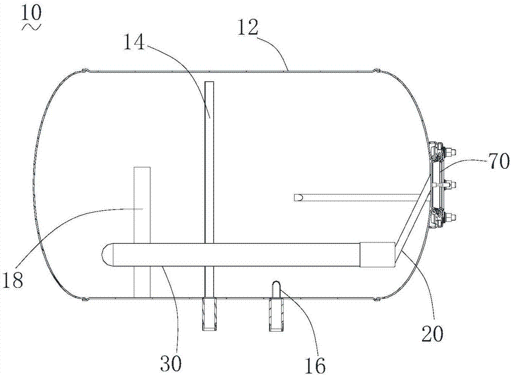
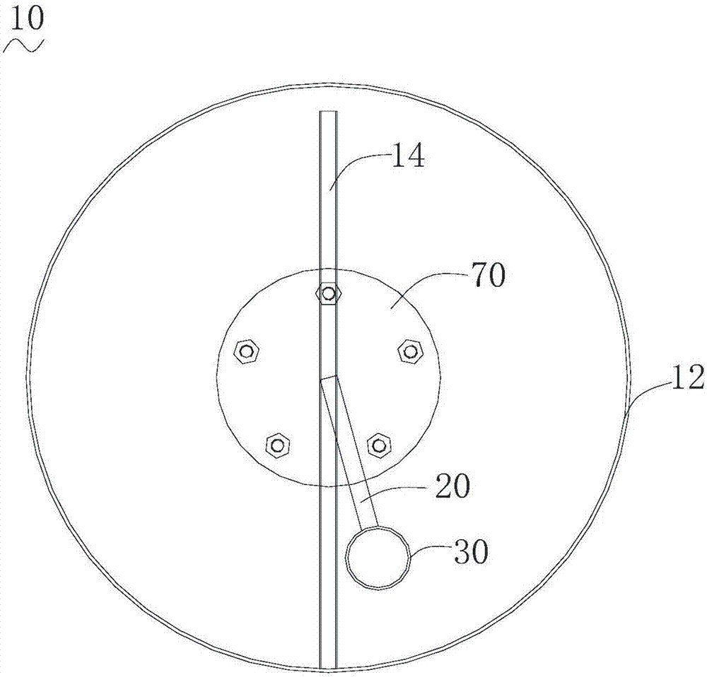
[0028] Such as figure 1 and figure 2 As shown, the inner container assembly 10 of a light wave electric water heater in an embodiment of the present invention includes a power source (not shown). The inner container assembly 10 includes an inner container body 12, a connecting tube 2, a sleeve 30, and a light wave electric water heater. Tube (not marked in the picture).
[0029] The connecting tube 20 is disposed in the inner cavity of the inner liner body 12. The sleeve 30 is located in the inner cavity of the inner liner body. The sleeve 30 includes a closed end and an open end. The open end is sealed and fixedly connected with the connecting pipe 20 so that the sleeve 30 communicates with the connecting pipe 20. The light wave tube includes a light wave tube main body 42 and a lead wire 43 drawn from one end of the light wave tube main body 42. The light wave tube main body 42 is arranged in the sleeve 30. The lead wire 43 passes through the open end and is led out through the connecting pipe 20 to connect with the light wave electric water heater. Power connection.
[0030] In the inner container assembly 10 of the light wave electric water heater, the light wave tube main body 42 of the light wave tube is arranged in the sleeve 30, and the lead wire 43 of the light wave tube is led out through the connecting tube 20 to connect with the power source of the light wave electric water heater to provide electric energy for the light wave tube. The light wave tube radiates far-infrared light waves to heat the water in the inner tank body 12, thereby realizing the conversion of "electric energy-light energy-heat energy". The water is directly heated by light waves, reducing energy loss, and heating speed is fast. In addition, the light wave tube is sealed in the sleeve 30, and its lead wire 43 is also sealed in the connecting tube 20 and led out, which prevents the light wave tube from contacting the water in the inner tank body 12 and completely realizes the separation of water and electricity. The phenomenon of electricity leakage and water charging is eliminated, and the safety of the light wave electric water heater is improved.
[0031] In one embodiment, the open end of the sleeve 30 and the connecting tube 20 are filled with a specific elastic sealant 50, which serves to fix the lightwave tube and further seal the sleeve 30 and the connecting tube 20. Specifically, the sealant 50 is organic silica gel, which has the properties of low expansion coefficient, high thermal conductivity and high temperature resistance.
[0032] Further, the liner assembly 10 further includes an elastic member 60 disposed in the sleeve 30. One end of the lightwave tube main body 42 abuts against the sealant 50, and the other end abuts against the elastic member 60. The elastic member 60 is far away from the lightwave tube main body 42. One end of the tube abuts against the closed end of the sleeve 30 to provide a pre-tensioning force for the light wave tube main body 42 to move along the sleeve toward the connecting tube 20. In this way, it is convenient to locate and fix the lightwave tube main body 42 at the center position of the sleeve 30, and has an anti-vibration effect. Specifically, the elastic member 60 is a spring.
[0033] In an embodiment, the liner assembly 10 further includes a flange seat 70, and the connecting pipe 20 is installed on the liner body 12 through the flange seat 70.
[0034] Specifically, the liner body 12 defines a mounting hole (not shown), the flange seat 70 is installed in the mounting hole, and the connecting pipe 20 is installed on the flange seat 70 and communicates with the outside of the liner body 12.
[0035] In one embodiment, the lightwave tube main body 42 includes a sealed outer tube (not shown) and a carbon fiber heating wire 45 arranged in the outer tube. The lead wire 43 includes two wires. The two ends of the carbon fiber heating wire 45 are connected to the two lead wires 43 respectively. Electric connection. Specifically, the carbon fiber heating wire 45 extends along the spiral line to form a spiral body, and a lead 43 is connected to the end of the carbon fiber heating wire 45 near the closed end, and is led out to the open end along the axis of the spiral body, and then is led out to the inner tank body 12 through the connecting tube 20 The other lead 43 is connected to the end of the carbon fiber heating wire 45 close to the open end, and is led out of the inner tank body 12 through the open end and the connecting tube 20. The two leads 43 are used to connect with the power supply of the light wave electric water heater to provide the light wave tube Electrical energy.
[0036] Specifically, the material of the outer tube is dehydroxylated quartz glass, which has high light transmittance, low thermal expansion coefficient, high stability, can withstand severe temperature changes, and has good insulation and sealing, which further strengthens the separation of water and electricity. , Improve the safety of light wave electric water heater.
[0037] Specifically, the outer tube is filled with inert gas.
[0038] In one embodiment, the liner assembly 10 further includes a sealing ring 90, the connecting tube 20 is sleeved on the open end of the sleeve 30, and the sealing ring 90 is provided between the connecting tube 20 and the sleeve 30 to seal the connecting tube 20 and At the connection of the sleeve 30, the connecting pipe 20 and the sleeve 30 are connected in a sealed manner to prevent the sealant 50 from overflowing.
[0039] Specifically, the material of the sleeve 30 is dehydroxylated quartz glass. In this way, the casing 30 has stable chemical properties, good acid and alkali resistance, and does not react with calcium and magnesium ions in the water even under high temperature and high pressure, so it does not scale and has a long service life.
[0040] Further, the liner assembly 10 further includes a reflective heat-insulating medium 80, which is wrapped around the end of the light wave tube main body 42 near the open end of the sleeve 30, so that the light wave tube main body 42 radiates to the open end of the sleeve 30 The light wave is reflected by the reflective heat insulation medium 80, which avoids direct radiant heating of the connection between the open end of the sleeve 30 and the connecting pipe 20, and reduces the thermal expansion of the sealing ring 90, the sealant 50 and the open end of the sleeve 30 , Which makes the sealing performance more stable and further improves the safety of the light wave electric water heater.
[0041] In one embodiment, the liner assembly 10 further includes a water inlet pipe 16, a water outlet pipe 14 and a magnesium rod 18 installed on the inner cavity side wall of the inner liner body 12, and the sleeve 30 and the water inlet pipe 16, the water outlet pipe 14 and The distance of the magnesium rod 18 is greater than or equal to a preset distance, so as to prevent the casing 30 from colliding with the water inlet pipe 16, the water outlet pipe 14 or the magnesium rod 18 during use or transportation.
[0042] Specifically, in one embodiment, the liner body 12 is cylindrical, and the connecting tube 20 is fixedly connected to one end of the liner body 12 and is arranged at an angle to the axis of the liner body 12. Further, the water inlet pipe 16, the water outlet pipe 14, and the magnesium rod 18 are arranged on the side wall of the inner liner body 12 at intervals along the axis of the liner body 12, and the connecting pipe 20 is located between the water inlet pipe 16, the water outlet pipe 14 and the magnesium rod 18 The plane is set at an angle to realize that the distance between the casing 30 and the water inlet pipe 16, the water outlet pipe 14 and the magnesium rod 18 is greater than or equal to a preset distance, thereby preventing the casing 30 and the water inlet pipe 16 during use or transportation. , The outlet pipe 14 or the magnesium rod 18 collides.
[0043] Based on the inner container assembly 10 of the light wave electric water heater, the present invention also provides a light wave electric water heater, including the inner container assembly 10 in any of the above embodiments.
[0044] In one embodiment, the light wave electric water heater further includes an outer shell, and the inner container assembly 10 is housed in the outer shell to protect the inner container assembly 10.
[0045] Further, the light wave electric water heater further includes an insulation layer arranged between the outer shell and the inner container body 12 to reduce the heat loss of the water in the inner container body 12.
[0046] In one embodiment, the light wave electric water heater further includes a control circuit connected between the end of the lead wire 43 leading out of the inner container body 12 and the power source to control the power source to provide power to the light wave tube body 42.
[0047] The technical features of the above-mentioned embodiments can be combined arbitrarily. In order to make the description concise, all possible combinations of the various technical features in the above-mentioned embodiments are not described. However, as long as there is no contradiction in the combination of these technical features, All should be considered as the scope of this specification.
[0048] The above-mentioned embodiments only express several embodiments of the present invention, and the descriptions are more specific and detailed, but they should not be understood as limiting the scope of the invention patent. It should be pointed out that for those of ordinary skill in the art, without departing from the concept of the present invention, several modifications and improvements can be made, and these all fall within the protection scope of the present invention. Therefore, the protection scope of the patent of the present invention should be subject to the appended claims.

PUM

no PUM

Description & Claims & Application Information

We can also present the details of the Description, Claims and Application information to help users get a comprehensive understanding of the technical details of the patent, such as background art, summary of invention, brief description of drawings, description of embodiments, and other original content. On the other hand, users can also determine the specific scope of protection of the technology through the list of claims; as well as understand the changes in the life cycle of the technology with the presentation of the patent timeline. Login to view more.

Similar technology patents

Subsea valve

ActiveUS20160003001A1eliminate leakage
Owner:AKER SOLUTIONS AS

Vented gas riser apparatus

InactiveUS20090236846A1eliminate leakage
Owner:ENERGY CONTROL SYST

Remote control zero clearing device of arrester counters

InactiveCN103604981ASimple structureEliminate leakage
Owner:MAINTENANCE COMPANY OF STATE GRID XINJIANG ELECTRIC POWER COMPANY

Device for protecting big data equipment by utilizing commercial power current characteristics

ActiveCN111585095AEliminate leakageReduce the resistance of the socket
Owner:山东凯迪欧电气有限公司

Power transformer with DC leakage protection

PendingCN107749612Aimprove securityEliminate leakage
Owner:毛春梅

Classification and recommendation of technical efficacy words

  • Eliminate leakage
  • improve security

Methods of making reclosable packages for vacuum, pressure and/or liquid containment

InactiveUS20060111226A1improve constructioneliminate leakage
Owner:ILLINOIS TOOL WORKS INC

Connectable chamber for porthole testing

InactiveCN1960907AImprove sealing performanceEliminate leakage
Owner:ГОСУДАРСТВЕННОЕ УЧРЕЖДЕНИЕ "ФЕДЕРАЛЬНОЕ АГЕНТСТВО ПО ПРАВОВОЙ ЗАЩИТЕ РЕЗУЛЬТАТОВ ИНТЕЛЛЕКТУАЛЬНОЙ ДЕЯТЕЛЬНОСТИ ВОЕННОГО +1

Method for preventing milling leakage of milling groove of circuit board

ActiveCN105228358AImprove efficiencyEliminate leakage
Owner:南通胜宏科技有限公司

Subsea valve

ActiveUS20160003001A1eliminate leakage
Owner:AKER SOLUTIONS AS

Device for protecting big data equipment by utilizing commercial power current characteristics

ActiveCN111585095AEliminate leakageReduce the resistance of the socket
Owner:山东凯迪欧电气有限公司

Pesticide micro-capsule granules and preparation method thereof

InactiveCN102100229Alow toxicityimprove security
Owner:联合国南通农药剂型开发中心 +1

Method for achieving user authentication by utilizing camera

InactiveCN103678984Aimprove securityGuaranteed picture quality
Owner:湖北微模式科技发展有限公司
Why Eureka
Try Eureka