

Vented gas riser apparatus
Patent Information
- Authority / Receiving Office
- US · United States
- Current Assignee / Owner
- ENERGY CONTROL SYST
- Publication Date
- 2009-09-24
- Estimated Expiration
- Not applicable · inactive patent
Smart Images
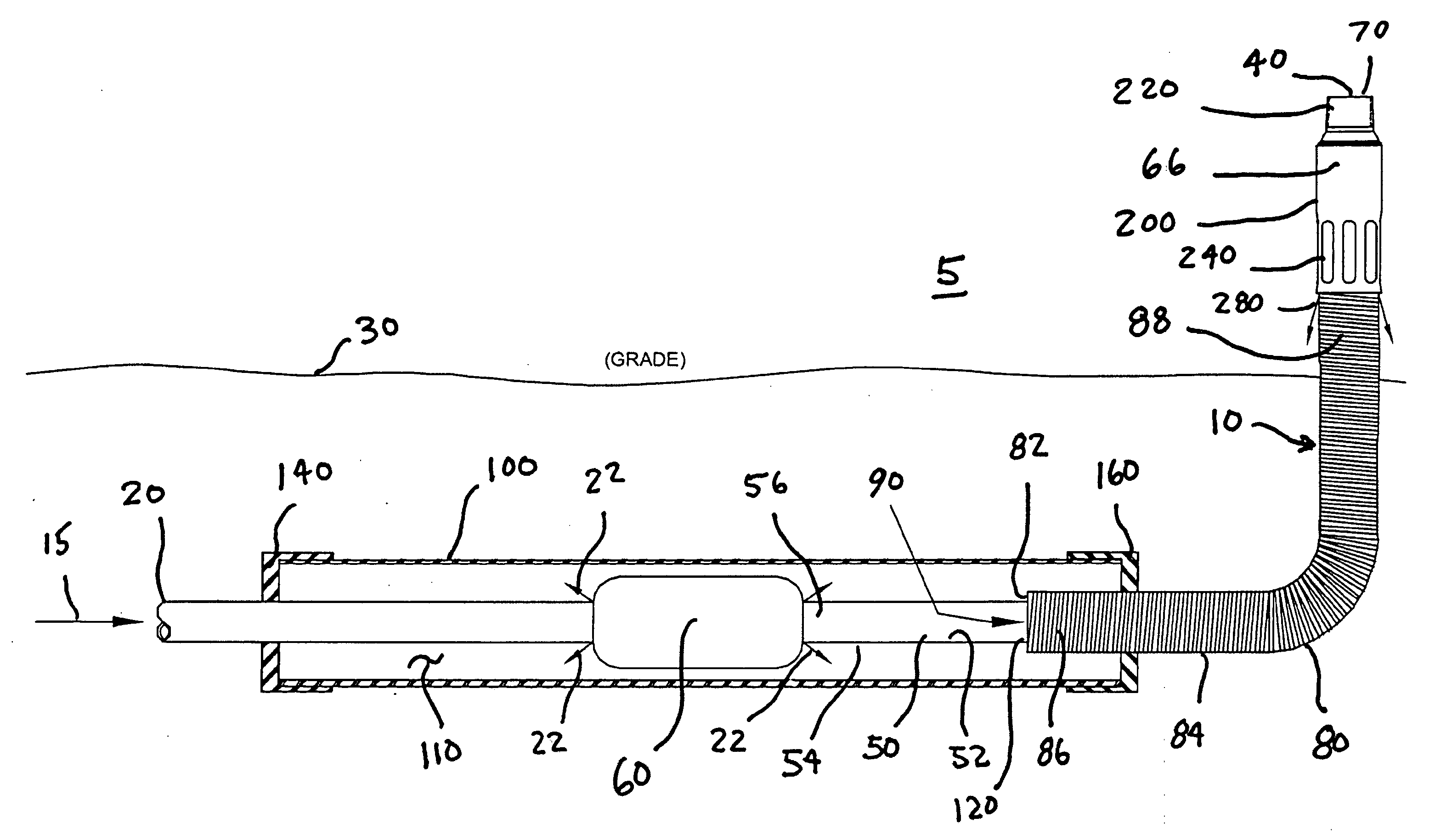
Figure 1 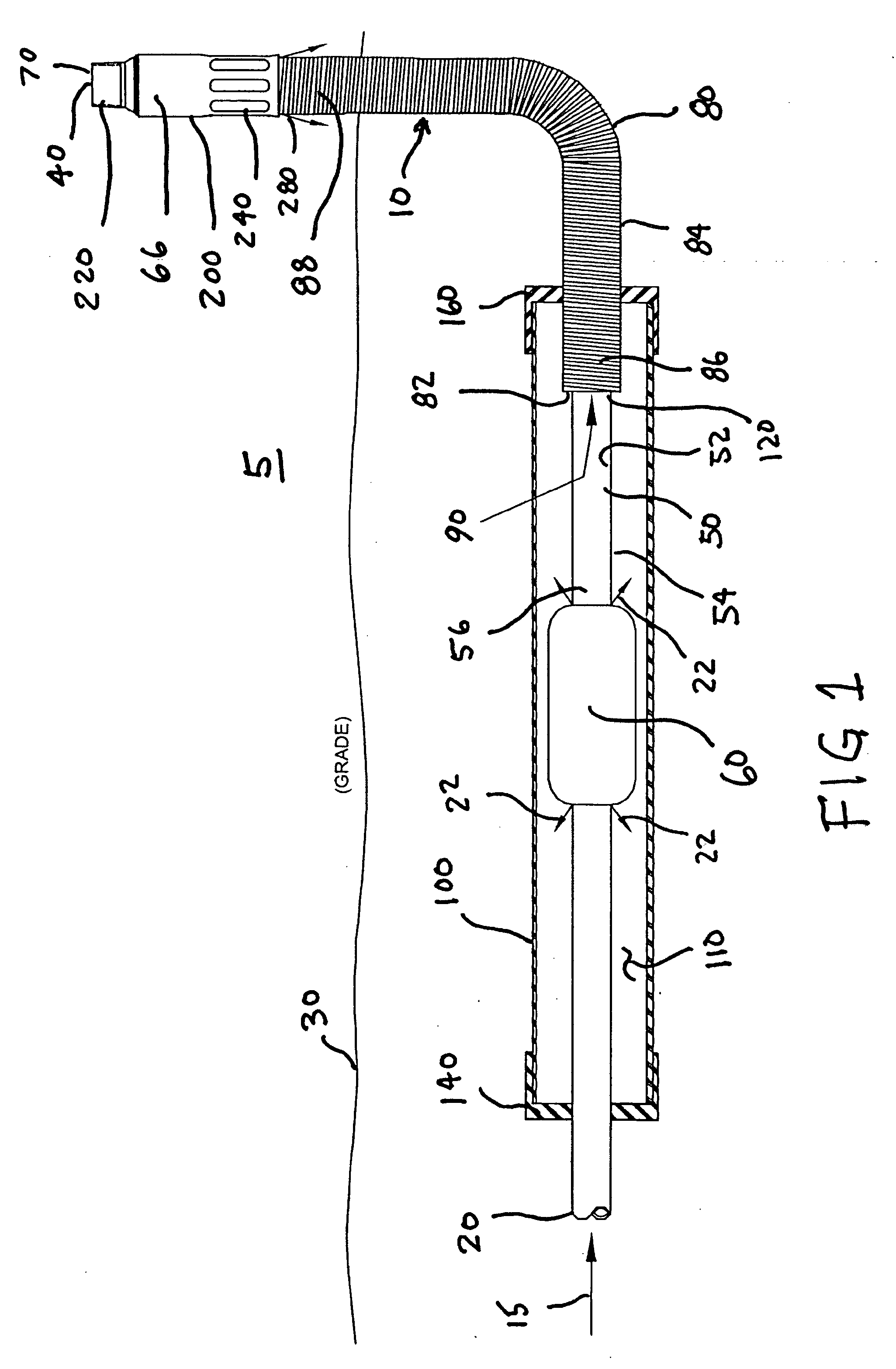
Figure 2 
Figure 3
Abstract
Description
BACKGROUND OF THE INVENTION
[0001] 1. Field of the Invention
[0002] This application is a continuation-in-part of U.S. patent application Ser. No. 12 / 077,628 filed Mar. 19, 2008. The present invention relates to a vented gas riser apparatus. More specifically, it relates to a vented gas riser apparatus which includes a buried containment chamber in combination with a vent passageway to allow for gas which leaks into the containment chamber to be directed into the atmosphere in at an above ground location. In another embodiment, the present invention also relates to a vented gas riser which provides a vent passageway to allow for gas which leaks into an extended gas escape passageway at any location along the length of a carrier pipe to be directed into the atmosphere in at an above ground location.
[0003] 2. Description of the Prior Art
[0004] A variety of prior art patents for various natural gas meter riser systems are known in the industry. For example, the following patents each describ...