

Power transformer with DC leakage protection
A power transformer, DC leakage technology, applied in transformer testing, emergency protection circuit devices, measurement of electrical variables, etc., can solve the problems of human safety hazards, leakage circuit breakers cannot detect DC leakage, and there is no safety protection circuit at the output end. The effect of improving safety, avoiding electric shock to users, and improving safety in use
- Summary
- Abstract
- Description
- Claims
- Application Information
AI Technical Summary
Problems solved by technology
Method used
Image

Examples
Embodiment 1
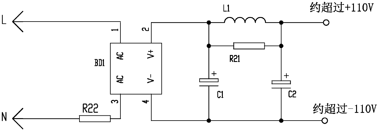
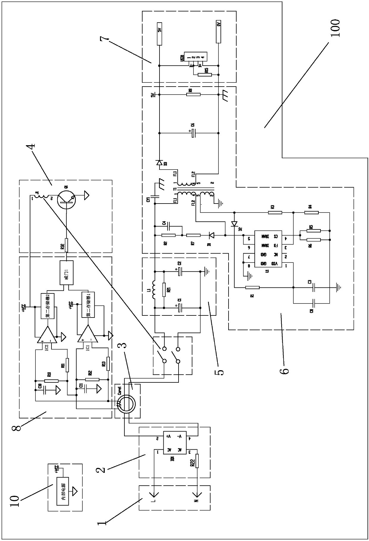
[0034] Such as image 3 As shown, the DC variable current circuit 2 is a rectifier bridge, and the DC bidirectional leakage detection circuit 3 is composed of an induction coil Core1, an amplifier IC1, and an amplifier IC2.
[0035] The DC bidirectional leakage detection circuit 3 is an induction coil Core1 set on the output end of the DC variable current circuit 2, and the output end of the induction coil Core1 is connected to an operation processing circuit 8, and the operation processing circuit 8 includes an amplifier IC1 and an amplifier IC2 , the first latch 1, the second latch 2, or gate 1, the output terminal of the amplifier IC1 is connected to the input terminal of the first latch 1, the negative input terminal of the amplifier IC1 is respectively connected to one end of the resistor R12 through the resistor R13, and the DC bidirectional One output end of the induction coil Core1 in the leakage detection circuit 3 is connected, the positive input end of the amplifier...
Embodiment 2
[0038] Such as Figure 4 As shown, the DC variable current circuit 2 is a rectifier bridge, and the DC bidirectional leakage detection circuit 3 is composed of an induction coil Core1 and an amplifier IC1, and the response speed of one amplifier circuit is slower than that of two amplifier circuits.
[0039] The DC bidirectional leakage detection circuit 3 is an induction coil Core1 set on the output end of the DC variable current circuit 2, and the output end of the induction coil Core1 is connected to an operation processing circuit 8, and the operation processing circuit 8 includes an amplifier IC1 and a first The latch 1, the output terminal of the amplifier IC1 is connected to the input terminal of the first latch 1, the negative input terminal of the amplifier IC1 is respectively connected to one end of the resistor R12 and an output terminal of the induction coil Core1 in the DC bidirectional leakage detection circuit 3 through a resistor R13, and the amplifier The posi...
Embodiment 3
[0042] Such as Figure 5 As shown, the DC variable current circuit 2 is a rectifier bridge, and the DC bidirectional leakage detection circuit 3 is composed of an induction coil Core1 and an amplifier IC1, and the response speed of one amplifier circuit is slower than that of two amplifier circuits.
[0043] The DC bidirectional leakage detection circuit 3 includes an induction coil Core1 and an induction coil Core2 respectively sleeved on the output end of the DC variable current circuit 2, and the output terminals of the induction coil Core1 and the induction coil Core2 are respectively connected with the arithmetic processing circuit 8, and the The operation processing circuit 8 includes an amplifier IC1, an amplifier IC2, a first latch 1, a second latch 2, and an OR gate 1. The output terminal of the amplifier IC1 is connected to the input terminal of the first latch 1, and the negative input terminal of the amplifier IC1 is The resistor R13 is respectively connected to on...
PUM
 Abstract
Description
Claims
Application Information