Fault diagnosis method and system for vibration equipment

A vibration equipment and fault diagnosis technology, which is applied in the testing of mechanical parts, the testing of machine/structural parts, instruments, etc., can solve problems such as difficulty in fault diagnosis, interference with equipment judgment, and unsatisfactory results of vibration fault diagnosis methods, and achieve accurate Fault diagnosis results and the effect of improving accuracy

Active Publication Date: 2021-11-30
NO 719 RES INST CHINA SHIPBUILDING IND
View PDF0 Cites 0 Cited by
  • Summary
  • Abstract
  • Description
  • Claims
  • Application Information

AI Technical Summary

Problems solved by technology

[0003] For some vibration equipment with asymmetric shape and aperiodic vibration signal, the existing equipment vibration fault diagnosis methods are not ideal
For example, there are many mechanical vibration equipment in ships with complex structures, and fault diagnosis is difficult. At present, there are few researches on fault diagnosis of marine asymmetric and aperiodic vibration equipment. Most of them focus on feature selection and feature transformation of original vibration information, which is difficult to obtain. Accurate fault diagnosis results, the main difficulty lies in: the fault diagnosis of ship mechanical vibration equipment is based on a large number of parameter information of equipment operation, usually a large amount of original vibration data is collected through various vibration sensors placed, and these original data not only contain a large amount of redundant information and interference information, and these raw data include the main feature information that plays a key role and the secondary feature information that plays an auxiliary role. Appropriate description of the vibration characteristics of asymmetric non-periodic vibration equipment, thus affecting the accuracy of the final fault diagnosis

Method used


Image

  • Fault diagnosis method and system for vibration equipment
  • Fault diagnosis method and system for vibration equipment
  • Fault diagnosis method and system for vibration equipment

Examples


Embodiment Construction

[0047] The present invention will be further described in detail below in conjunction with the accompanying drawings and specific embodiments.

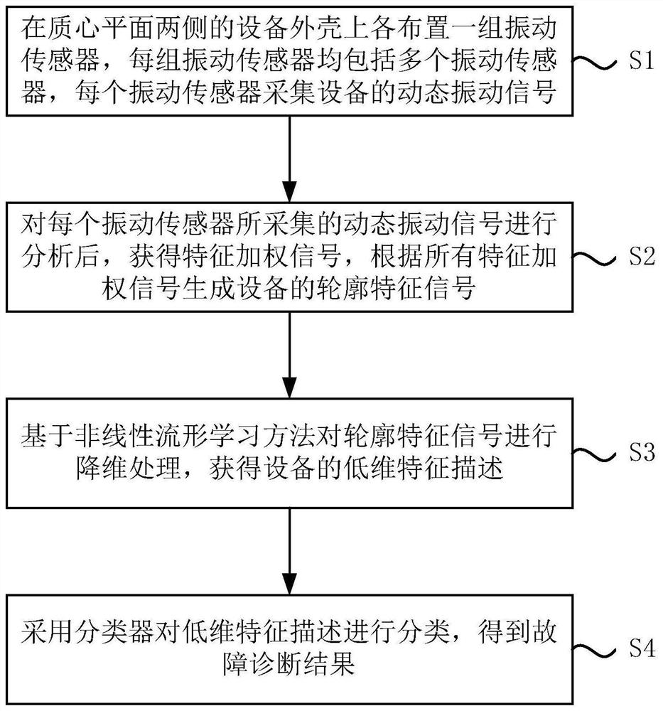
[0048] see figure 1 As shown, the present invention provides a fault diagnosis method for vibration equipment. The vibration equipment has aperiodic vibration and / or asymmetric shape. This fault diagnosis method can be used for aperiodic vibration equipment, asymmetric shape equipment and aperiodic vibration and shape For asymmetrical equipment, this fault diagnosis method includes:

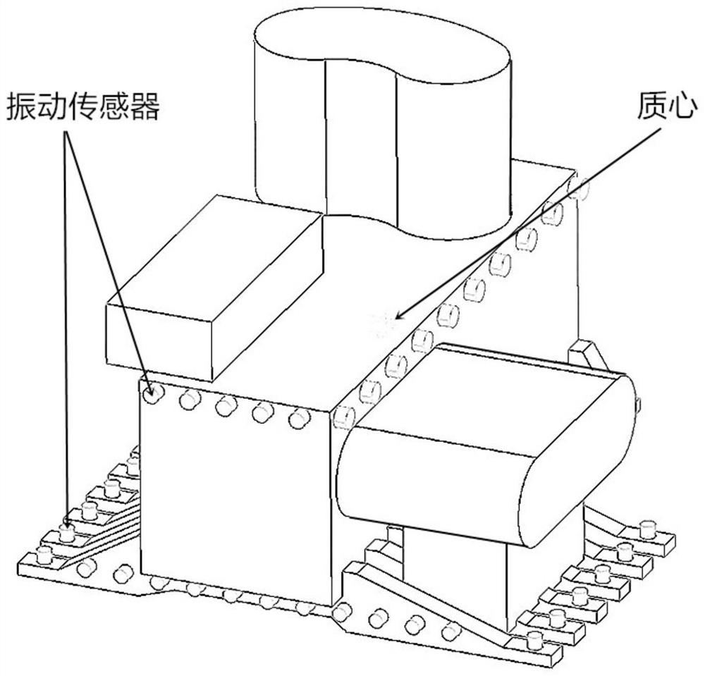
[0049] S1. Arrange a group of vibration sensors on the vibration equipment shells on both sides of the centroid plane, each group of vibration sensors includes a plurality of vibration sensors, each group of vibration sensors is arranged around a vertical axis, the vertical axis passes through the centroid and is perpendicular to the centroid plane, Each vibration sensor collects dynamic vibration signals of the vibration equipment, and the centroid pla...


PUM


Abstract

The invention discloses a fault diagnosis method and system of vibration equipment. The vibration equipment vibrates aperiodically and / or has an asymmetric shape, and relates to the field of equipment fault diagnosis. The method includes: respectively arranging a group of vibration sensors on the vibration equipment shell on both sides of the centroid plane, each group of vibration sensors includes a plurality of vibration sensors, each vibration sensor collects the dynamic vibration signal of the equipment, and the centroid plane is parallel to the vibration equipment base The plane where the seat is located; after analyzing the dynamic vibration signal collected by each vibration sensor, the characteristic weighted signal is obtained, and the contour characteristic signal of the vibration equipment is generated according to all the characteristic weighted signals; the contour characteristic signal is reduced based on the nonlinear manifold learning method. Dimensional processing to obtain the low-dimensional feature description of the vibration equipment; use a classifier to classify the low-dimensional feature description to obtain the fault diagnosis result. The invention effectively reduces the secondary and interference information in the original vibration data, and obtains stable and accurate fault diagnosis results.

Description

technical field [0001] The invention relates to the field of equipment fault diagnosis, in particular to a fault diagnosis method and system for vibration equipment. Background technique [0002] Fault diagnosis technology is widely used in the operation status analysis and health management of mechanical vibration equipment. At present, the fault diagnosis methods for mechanical vibration equipment are mostly for rotating vibration equipment, impact vibration equipment, reciprocating vibration equipment, etc. The original vibration of these equipment The information has obvious periodicity or changing characteristics, and the fault diagnosis is mostly to analyze the vibration signal in the frequency domain, such as Fourier transform, wavelet analysis, etc., or use methods such as neural networks, and some diagnostic methods will also combine the time domain information for feature-level fusion or decision-level fusion. [0003] For some vibrating equipment with asymmetric ...

Claims


Application Information

Patent Timeline
Patent Type & Authority Patents(China)
IPC IPC(8): G06K9/00G06K9/62G01M13/00
CPCG01M13/00G06F2218/08G06F18/254
Inventor 郑伟叶瑞平方明杰
Owner NO 719 RES INST CHINA SHIPBUILDING IND
Why Eureka
Try Eureka