
Heat dissipation sheet used for transformer

A technology of heat sink and transformer, applied in the direction of transformer/inductor cooling, etc., can solve the problems of poor heat dissipation effect of transformer heat sink and large footprint.

Inactive Publication Date: 2018-05-04
江苏瑞凌新能源科技有限公司
View PDF1 Cites 0 Cited by
  • Summary
  • Abstract
  • Description
  • Claims
  • Application Information

AI Technical Summary

Problems solved by technology

Traditional transformer heat sinks have poor heat dissipation and occupy a large area

Method used


Image

  • Heat dissipation sheet used for transformer

Examples


Embodiment Construction

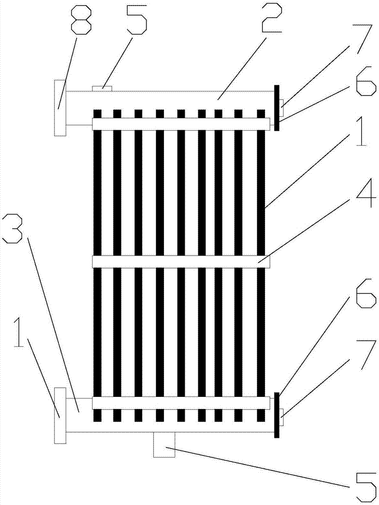
[0011] like figure 1 The shown heat sink for a transformer is mainly composed of a heat sink 1, an upper oil collection pipe 2, a lower oil collection pipe 3, a reinforcing rib 4, an oil drain plug 5 and a plug 6; the heat sink 1 is arranged in parallel, and the upper oil collection pipe 2 It is arranged on the upper end of the cooling fin 1, the lower oil collecting pipe 3 is arranged on the lower end of the cooling fin 1, the reinforcing rib 4 is vertically connected on the cooling fin 1, the oil drain plug 5 is arranged on the upper oil collecting pipe 2, and the lower oil collecting pipe 3 is also provided with Oil drain plug 5; Plug 6 is arranged on one end of upper oil collecting pipe 2 and lower oil collecting pipe 3.

[0012] Wherein the outer side of the plug 6 is also provided with a connecting nut 7 . The other ends of the upper oil collecting pipe 2 and the lower oil collecting pipe 3 are also provided with a plastic cover 8 .

[0013] Although the specific embod...


PUM


Abstract

The invention relates to a heat dissipation sheet used for a transformer. The heat dissipation sheet mainly consists of heat dissipation sheets, an upper oil collecting pipe, a lower oil collecting pipe, reinforcing ribs, oil discharging plugs and plugs, wherein the heat dissipation sheets are arranged in parallel; the upper oil collecting pipe is arranged at the upper ends of the heat dissipationsheets; the lower oil collecting pipe is arranged at the lower ends of the heat dissipation sheets; the reinforcing ribs are perpendicularly connected with the heat dissipation sheets; one oil discharging plug is arranged on the upper oil collecting pipe; one oil discharging plug is arranged on the lower oil collecting pipe; and the plugs are arranged at one ends of the upper oil collecting pipeand the lower oil collecting pipe respectively. By adoption of the structure, short heat dissipation time and high heat dissipation effect are achieved, and the service life of the transformer can beprolonged.

Description

technical field [0001] The invention relates to a cooling fin for a transformer. technical background [0002] Transformer is a device that uses the principle of electromagnetic induction to change AC voltage. The main components are primary coil, secondary coil and iron core. The main functions are: voltage conversion, current conversion, impedance conversion, isolation, voltage stabilization, etc. According to the purpose, it can be divided into: power transformers and special transformers. Circuit symbols often use T as the beginning of the number. Example: T01, T201, etc. Traditional transformer heat sinks have poor heat dissipation and occupy a large area. Contents of the invention [0003] The technical problem to be solved in the present invention is a heat sink for a transformer proposed in view of the above technical problem. [0004] In order to solve the above-mentioned technical problems, the present invention provides a cooling fin for a transformer, which...

Claims


Application Information

Patent Timeline
IPC IPC(8): H01F27/12H01F27/22
CPCH01F27/12H01F27/22
Inventor 田金虎
Owner 江苏瑞凌新能源科技有限公司
Learn More