

Circuit breaker
A technology for circuit breakers and disconnecting circuits, applied in circuits, logic controllers for automation/industrial process control, sealed enclosures, etc., can solve the problems of canceling protection, destroying equipment components, etc., and achieve the effect of a simple actuator
- Summary
- Abstract
- Description
- Claims
- Application Information
AI Technical Summary
Problems solved by technology
Method used
Image


Examples
Embodiment Construction
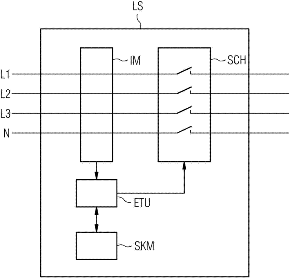
[0053] figure 1 Functional block representing a circuit breaker LS for a circuit or circuit system, for example for a three-phase system comprising conductors L1, L2, L3 and N, which are connected to the circuit breaker LS and their current flows through the circuit breaker device LS. A sensor device IM is provided in the circuit breaker LS, which determines circuit parameters such as current or / and voltage or / and frequency.
[0054] The sensor device IM is connected to the electronic triggering device ETU, which detects the exceeding of safety parameters. The safety parameter can be a current limit value or / and a current-time-limit value or / and a voltage limit value or / and a mathematical combination thereof.
[0055] The electronic triggering unit ETU is connected to the contacting device SCH, which serves to break the current of the circuit or the circuit system.
[0056]If the electronic triggering unit ETU detects that a parameter, such as a measured value of the sensor...
PUM
 Abstract
Description
Claims
Application Information