
Electromechanical actuator for a brake

a technology of electric actuator and brake, which is applied in the direction of braking system, aircraft braking arrangement, structural association, etc., can solve the problems of increasing the cost of the actuator, complex management of interfaces and connection harnesses, etc., and achieve the effect of simplifying the actuator

Active Publication Date: 2017-02-14
SAFRAN LANDING SYSTEMS
View PDF12 Cites 0 Cited by
  • Summary
  • Abstract
  • Description
  • Claims
  • Application Information

AI Technical Summary

Benefits of technology

This solution enables seamless electrical connectivity between the actuator portions and external control means without additional connectors, facilitating easy separation and replacement of faulty parts, reducing complexity and cost while maintaining reliable operation.

Problems solved by technology

A second connector is thus added to the actuator, thereby increasing its cost and making the management of interfaces and the connection harness more complex.

Method used


Image

  • Electromechanical actuator for a brake
  • Electromechanical actuator for a brake

Examples


Embodiment Construction

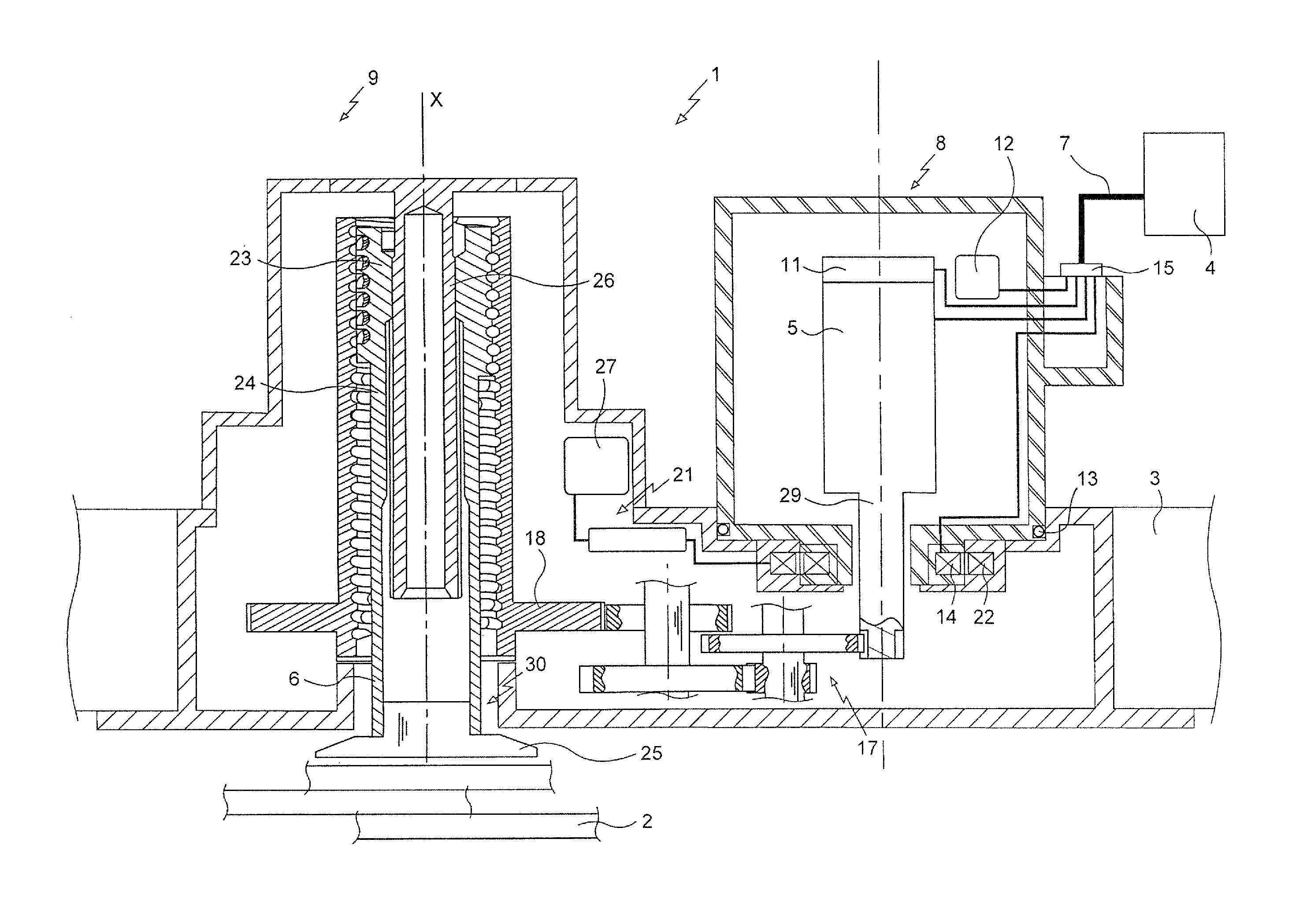
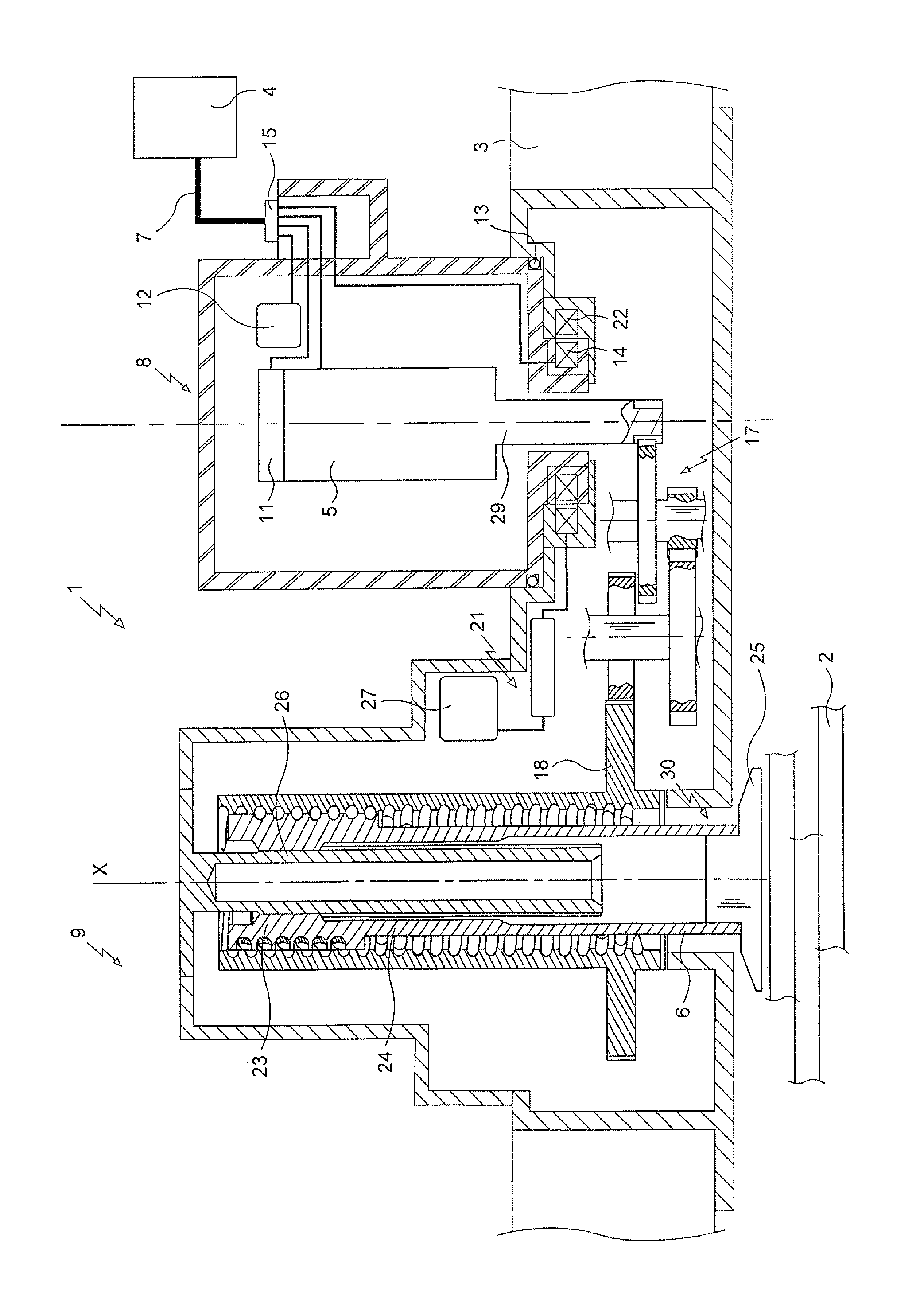
[0010]An electromechanical actuator 1 of the invention is for selectively applying a braking force on friction members 2 of a brake of an aircraft wheel, specifically a stack of carbon disks. This actuator 1 is mounted on an actuator carrier 3 of the brake and it is fastened to the actuator carrier by fastener means that are not shown in the FIGURE.

[0011]The actuator 1 is controlled by external control means 4 that receive a braking setpoint, determining the braking force to be applied, and they generate electrical control power for controlling an electric motor 3 of the actuator 1 as a function of the braking force. The electric motor 5 then moves a pusher 6 facing the stack of disks 2 in order to apply the braking force to the stack of disks 2.

[0012]In order to transmit this electrical control power, the actuator 1 is connected to the control means 4 by a connection harness 7. The actuator carrier 3 optionally includes a connection unit connected to all of the actuators of the bra...


PUM


Abstract

An electromechanical actuator for a vehicle brake, the actuator comprising first and second portions 8 and 9 that are separable. The first portion 8 includes an electric motor 5 and connection structure 15 for connecting the actuator to an external control structure 4. The second portion 9 including a slidable pusher 6, the second portion 9 also including measurement structure 21. The first portion 8 includes a first antenna 14 connected to the connection structure 15, and the second portion 9 includes a second antenna 22 connected to the measurement structure 21, the two antennas 14, 22 being arranged to be electromagnetically coupled together when the first portion 8 and the second portion 9 are coupled together, so as to enable electrical signals to be transferred between the measurement structure 21 and the connection structure 15.

Description

[0001]The invention relates to an electromechanical actuator for a vehicle brake, the actuator comprising two portions that are separable.BACKGROUND OF THE INVENTION[0002]In an electrical braking system for an aircraft, each braked wheel is provided with a brake having friction members, generally a stack of carbon disks stacked around a torsion tube, and electromechanical actuators carried by an actuator carrier and controlled to apply a braking force on the friction members in order to exert a braking torque on the wheel tending to slow the aircraft down.[0003]Each electromechanical actuator is electrically powered and controlled by external control means. An actuator generally includes a pusher, an electric motor adapted to move the pusher in register with friction members, a blocking member for blocking the pusher in position, and sensors associated with the motor (position sensor, etc.) or with the pusher (force sensor, thermocouple, etc.). In order to control the electric motor...

Claims


Application Information

Patent Timeline
Patent Type & Authority Patents(United States)
IPC IPC(8): B60T13/74F16D65/16H02K7/116H02K7/06F16D65/18B64C25/44F16D66/00F16D121/24
CPCB60T13/746F16D65/16F16D65/18H02K7/06H02K7/116H02K11/24H02K11/35B64C25/44F16D2066/005F16D2121/24
Inventor RICHARD, NATHANAELEVENOR, ERICSELLES, FRANCK
Owner SAFRAN LANDING SYSTEMS
Learn More