Symbol judging method, symbol judging circuit and digital receiving circuit

A technology for judging circuits and symbols, applied in digital transmission systems, electrical components, modulated carrier systems, etc., can solve the problem of rising error rates in communication systems, reducing the performance of communication systems, and the inability of conventional digital receivers or symbol judgers to be correct Ground demodulation modulation signal and other issues

Active Publication Date: 2018-05-04
MEDIATEK INC
View PDF5 Cites 2 Cited by
  • Summary
  • Abstract
  • Description
  • Claims
  • Application Information

AI Technical Summary

Problems solved by technology

[0005] Conventional technology has not developed a corresponding demodulation method for irregular modulation methods, that is to say, conventional digital receivers or symbol judgers cannot correctly demodulate the modulation transmitted by the transmitter signal, which increases the error rate of the communication system and reduces the overall performance of the communication system

Method used


Image

  • Symbol judging method, symbol judging circuit and digital receiving circuit
  • Symbol judging method, symbol judging circuit and digital receiving circuit
  • Symbol judging method, symbol judging circuit and digital receiving circuit

Examples


Embodiment Construction

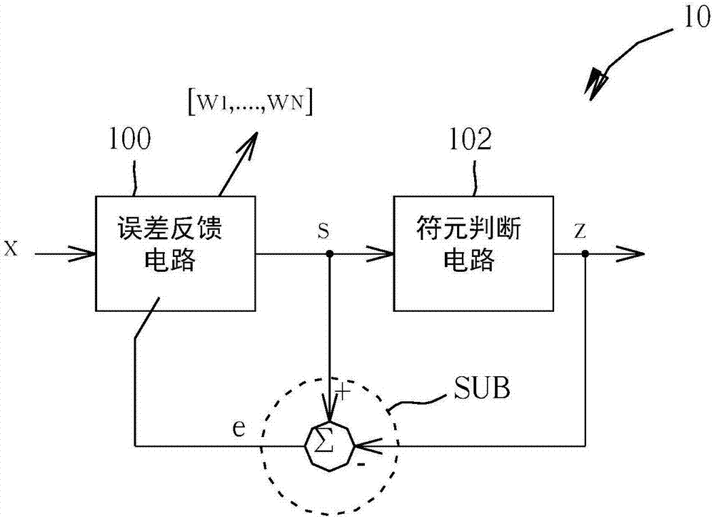
[0041] Please refer to figure 1 , figure 1 It is a block diagram of a digital receiving circuit 10 according to an embodiment of the present invention, as figure 1 As shown, the digital receiving circuit 10 includes an error feedback circuit 100 , a symbol determination circuit 102 and a subtraction unit SUB. The error feedback circuit 100 includes an adaptive filter (Adaptive Filter, not shown in figure 1 ), which can perform a signal processing on a signal x, that is, according to the coefficient w 1 ~w N Signal processing is performed on the signal x to output a first signal s. The symbol judging circuit 102 is a slicer (Slicer), which is coupled to the error feedback circuit 100. The symbol judging circuit 102 receives the first signal s, and judges a first signal corresponding to the first signal s according to the first signal s. A symbol (Symbol) z. The subtraction unit SUB is coupled to the error feedback circuit 100 and the symbol judgment circuit 102, and i...


PUM


Abstract

The invention discloses a symbol judging method. The symbol judging method comprises the following steps: storing a comparison table in a symbol judging circuit; receiving a first signal, and generating a coordinate signal group corresponding to the first signal according to the first signal, wherein the coordinate signal group is positioned in a first decision area; and reading the comparison table according to the coordinate signal group to output a first symbol corresponding to the first signal, wherein the first symbol is a first constellation point corresponding to the first decision area.

Description

technical field [0001] The present invention refers to a symbol judging method, a symbol judging circuit and a digital receiving circuit, especially a symbol judging method, a symbol judging circuit and Digital receiving circuit. Background technique [0002] Digital communication systems have been widely used in daily life. Conventional digital communication systems mostly use Regular Modulation Scheme (Regular Modulation Scheme) to modulate signals, such as BPSK, QPSK, 16PSK, 64PSK, 64QAM, 256QAM, etc. Way. Since the arrangement of the constellation points in the regular modulation method on a constellation plane is relatively regular, the demodulator (Demodulator) or symbol determiner (ie, slicer) corresponding to the regular modulation method is relatively simple. [0003] However, with people's demand for the transmission rate of the communication system, the new generation of communication system (such as the digital TV system DVB S2X) has begun to use high-order mod...

Claims


Application Information

Patent Timeline
Patent Type & Authority Applications(China)
IPC IPC(8): H04L27/34
CPCH04L27/345
Inventor 陈家伟苏裕哲童泰来
Owner MEDIATEK INC
Why Eureka
Try Eureka