AI technical title is built by Patsnap AI team. It summarizes the technical point description of the patent document.
A technology of printing platform and printing plate, applied in processing platform/substrate, additive processing, etc., can solve problems such as low efficiency and achieve the effect of continuous printing
Active Publication Date: 2018-05-08
福建万象三维科技有限公司
View PDF7 Cites 1 Cited by
Summary
Abstract
Description
Claims
Application Information
AI Technical Summary
This helps you quickly interpret patents by identifying the three key elements:
Problems solved by technology
Method used
Benefits of technology
Problems solved by technology
[0002] Existing 3D printing equipment only has one printing platform, and only one platform can be printed at a time. After the printing is completed, the printed object must be manually taken out before it can be printed again, which is inefficient.
Method used
Image
Click on the blue label to locate the original text in one second.
Reading with bidirectional positioning of images and text.
Examples
Embodiment 1
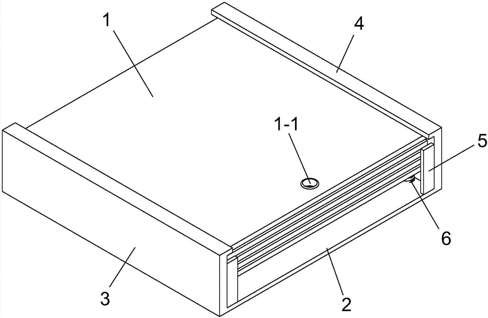
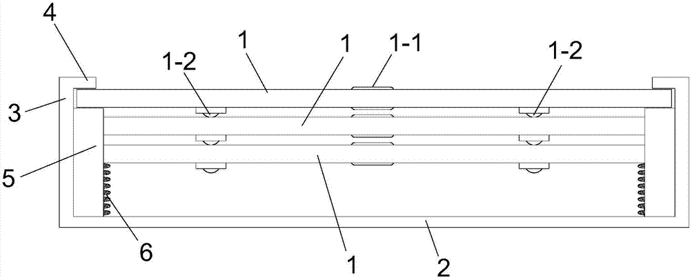
[0030] Such as Figure 1-4 As shown, the bottom surface of the printing plate 1 is provided with a sliding member 1-2 that slides and rubs against the upper side of the printing plate 1 on the lower layer.
[0031] Preferably, the sliding member 1-2 can be a ball.
[0032] There are four sliders 1-2 in total, which are respectively arranged on the peripheral side of the printing plate 1.
[0033] A baffle 5 is provided on the front and / or rear of the fixing bracket, and the baffle 5 blocks the front or rear of the printing plate 1 below the uppermost layer.
[0034] The arrangement of the sliders 1-2 can reduce the horizontal friction force between the upper and lower printing plates 1 .
[0035] The setting of the baffle plate 5 limits the displacement in the horizontal direction of the printing plate 1 below the second layer, so that it can only complete the vertical displacement.
Embodiment 2
[0037] Such as Figure 5-10 As shown, a number of barriers 7 are also provided between the printing plates 1, and the inner wall of the side plate 3 is provided with a vertically extending limiting track 3-1;
[0038] The barrier member 7 is slidably arranged in the limit track 3-1, and the barrier member 7 extends into the fixed bracket, and the upper and lower parts of the segment of the barrier member 7 extend into contact with the printing plate 1;
[0039] The limit plate 4 is provided with a through hole 4-1 through which the spacer 7 passes through corresponding to the position of the limit track 3-1.
[0040] The inner wall of the side plate 3 is provided with at least two limit rails 3-1, and each limit rail 3-1 is spaced in front and back.
[0041] The barrier 7 is T-shaped, and the limiting track 3-1 is a T-shaped track.
[0042] The upper and lower surfaces of the barrier member 7 are smooth surfaces.
[0043] A barrier member 7 is provided between the upper and...
PUM
Abstract
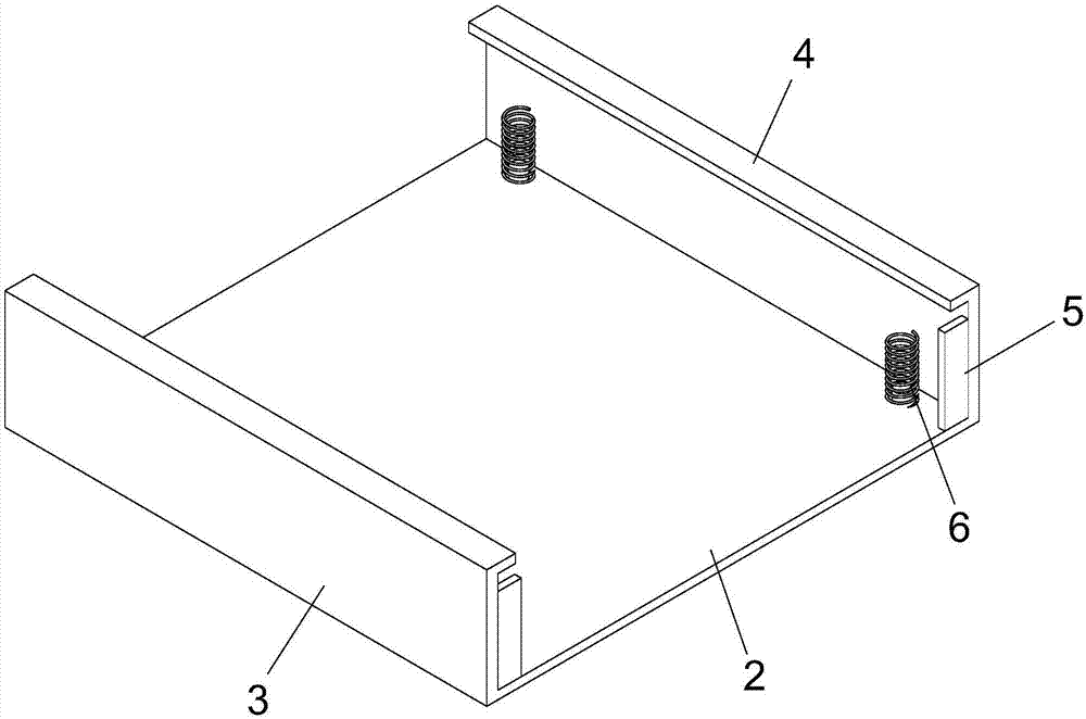
The invention relates to a three-dimensional continuous printing platform device which comprises a fixed support and a plurality of printing flat plates, wherein the printing flat plates are stacked up and down, and the fixed support comprises a supporting bottom plate and two side plates arranged on the left side and the right side of the supporting bottom plate. A limiting plate which is parallel with the supporting bottom plate and extends back and forth is arranged at the upper end of each side plate, and a space is left between the left limiting plate and the right limiting plate to forma print area. The invention aims at providing the three-dimensional continuous printing platform device. The three-dimensional continuous printing platform device has the advantages that the printingflat plates are pressed on the bottom surfaces of the limiting plates of the fixed support through elastic elements, and a fixed hole into which a print head is inserted is formed in each printing flat plate; when the flat plate is replaced, only the print head is controlled to be inserted into the fixed hole, the flat plate is taken away through the print head; and at the moment, the second layerof printing flat plate is pressed by the elastic elements to rise to the topmost layer, and therefore the continuous printing of a three-dimensional printer is realized.
Description
technical field [0001] The invention relates to the field of three-dimensional printing, in particular to a three-dimensional continuous printing platform device. Background technique [0002] Existing 3D printing equipment only has one printing platform, and can only print objects on one platform at a time. After the printing is completed, the printed object must be manually taken out before it can be printed again, which is inefficient. Contents of the invention [0003] The purpose of the present invention is to provide a three-dimensional continuous printing platform device. [0004] The purpose of the present invention is achieved through the following technical solutions: a three-dimensional continuous printing platform device, which includes a fixed bracket and a number of printing plates arranged up and down stacked; the fixed bracket includes a support base plate and two side plates arranged on the left and right sides of the support base plate ; The top of the s...
Claims
Application Information
Patent Timeline
Application Date:The date an application was filed.
Publication Date:The date a patent or application was officially published.
First Publication Date:The earliest publication date of a patent with the same application number.
Issue Date:Publication date of the patent grant document.
PCT Entry Date:The Entry date of PCT National Phase.
Estimated Expiry Date:The statutory expiry date of a patent right according to the Patent Law, and it is the longest term of protection that the patent right can achieve without the termination of the patent right due to other reasons(Term extension factor has been taken into account ).
Invalid Date:Actual expiry date is based on effective date or publication date of legal transaction data of invalid patent.

