
Power transmission system and vehicle with same

A power transmission system and vehicle technology, applied in the field of power transmission system, can solve the problems of insufficient power and passing ability of the whole vehicle, low driving transmission efficiency, low power generation efficiency, etc., so as to improve the passing ability and escape ability, and enrich the driving mode , The effect of high transmission efficiency

Active Publication Date: 2018-05-08
BYD CO LTD
View PDF6 Cites 0 Cited by
  • Summary
  • Abstract
  • Description
  • Claims
  • Application Information

AI Technical Summary

Problems solved by technology

[0003] However, in the relevant technologies known to the inventor, some hybrid electric vehicles have few driving modes and low drive transmission efficiency, which cannot meet the requirements of the vehicle to adapt to various road conditions, especially after the hybrid electric vehicle is fed (when the battery power is insufficient). Insufficient vehicle power and passing capacity
Moreover, in order to realize the parking power generation condition, it is necessary to additionally increase the transmission mechanism, which has low integration and low power generation efficiency

Method used


Image

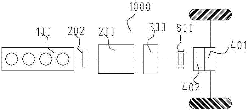
  • Power transmission system and vehicle with same
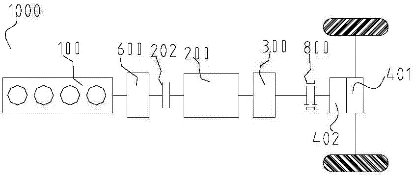
  • Power transmission system and vehicle with same
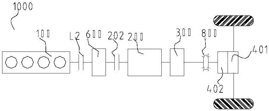
  • Power transmission system and vehicle with same

Examples


no. 3 Embodiment

[0057] According to the third specific embodiment of the present invention, it is substantially the same as the first specific embodiment, and for specific differences, refer to the following content. Such as Figure 13-Figure 18 As shown, in the axial direction of the central axis of the planetary gear mechanism P, the switching device adapter S is located on one side of the planetary gear mechanism P. Specifically, as Figure 13-Figure 15 As shown, the conversion device adapter S is located on the right side of the planetary gear mechanism P in the axial direction of the central axis of the planetary gear mechanism P. Such as Figure 16-Figure 18 As shown, the conversion device adapter S is located on the left side of the planetary gear mechanism P in the axial direction of the central axis of the planetary gear mechanism P. In this way, in the axial direction, the planetary gear mechanism P and the conversion device adapter S are spaced apart, so that the arrangement of ...


PUM


Abstract

The invention discloses a power transmission system and a vehicle with the same. The power transmission system includes a power source, a speed change unit, a first motor generator, a speed change unit output part, a system power output part, a mode conversion device and a power switching device; the first motor generator is in dynamic coupled connection with the speed change unit; the speed change unit output part is constructed to be suitable for outputting power output by the speed change unit; the speed change unit output part is in dynamic coupled connection or disconnection with the system power output part through the mode conversion device, the speed change unit output part is in dynamic coupled connection with the system power output part through the mode conversion device, and the mode conversion device is suitable for conducting speed reduction on power received by the speed change unit output part and output the power to the system power output part; the speed change unit is in dynamic coupled connection or disconnection with the speed change unit and the speed change unit output part through the power switching device. In this way, the driving modes of the vehicle canbe enriched, and the vehicle can adapt to different road conditions.

Description

technical field [0001] The present invention relates to the technical field of vehicles, in particular to a power transmission system of a vehicle and a vehicle with the power transmission system. Background technique [0002] With the continuous consumption of energy, the development and utilization of new energy vehicles has gradually become a trend. As one of the new energy vehicles, a hybrid vehicle is driven by an engine and / or an electric motor, and has multiple modes, which can improve transmission efficiency and fuel economy. [0003] However, in the related technologies known to the inventor, some hybrid electric vehicles have few drive modes and low drive transmission efficiency, which cannot meet the requirements of the vehicle to adapt to various road conditions, especially after the hybrid electric vehicle is powered (when the battery power is insufficient). The power and passing capacity of the whole vehicle are insufficient. Moreover, in order to realize the...

Claims


Application Information

Patent Timeline
Patent Type & Authority Applications(China)
IPC IPC(8): B60K6/365B60K6/54B60L11/14B60L50/16
CPCB60L50/16B60K6/365B60K6/54B60K6/36B60K6/48B60K2006/4825B60K6/387B60K6/547F16H3/006F16H37/046B60K1/02F16H2200/0052F16H2037/045B60K1/00B60K2001/001Y02T10/62B60K2006/542B60Y2200/92Y02T10/7072
Inventor 廉玉波凌和平翟震徐友彬黄威
Owner BYD CO LTD
Learn More