Eureka AIR delivers breakthrough ideas for toughest innovation challenges, trusted by R&D personnel around the world.

Big grid pattern conveyer belt joint structure and method

A checkered pattern and conveyor belt technology, used in conveyors, transportation and packaging, belt fasteners, etc., can solve the problems of inability to obtain continuous and full patterns, uneven unevenness, and achieve convenient distinction, convenient cutting, Checkered pattern joins natural effect

Inactive Publication Date: 2018-05-08
SHANGHAI YONGLI BELTING
View PDF0 Cites 0 Cited by
  • Summary
  • Abstract
  • Description
  • Claims
  • Application Information

AI Technical Summary

Problems solved by technology

[0006] 2) Use the pattern mold to align the pattern on the side of the upper joint, try to ensure that most of the patterns are qualified, and the other end that is not aligned with the pattern will be uneven, so it is impossible to get a continuous and full pattern

Method used


Image

  • Big grid pattern conveyer belt joint structure and method
  • Big grid pattern conveyer belt joint structure and method
  • Big grid pattern conveyer belt joint structure and method

Examples


Embodiment 1

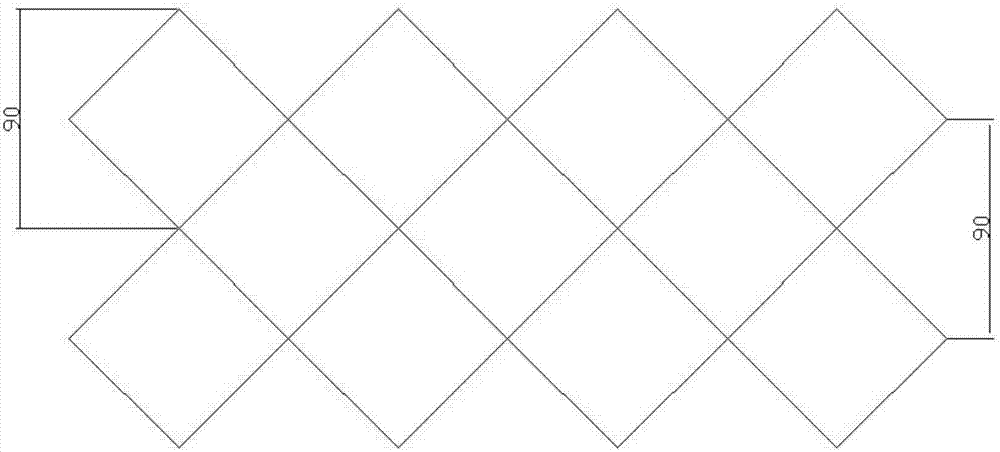
[0029] see figure 2 and 5 , the raised continuous large grid pattern on the conveyor belt, a pair of diagonal directions of the large grid are along the length and width of the conveyor belt, and the diagonal length of the large grid is 90mm; the conveyor belt is tiled, one end Cut along the diagonal of the large square; after the link size of the conveyor belt plus the joint allowance, divide by 90mm to produce a remainder ≤ 15, then the other end of the conveyor belt is also cut along the diagonal of the large square, that is, along the attached Figure 5 The line marked 4 is cut and looped to form figure 2 Joint Pattern Shown: Original large checkered pattern retained at the joint.

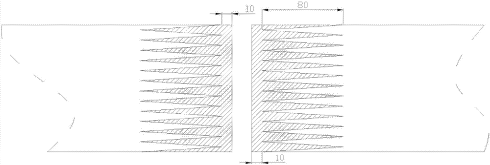
[0030] After the cutting is completed, the following process steps are sequentially included: layering, punching, positioning, and hot pressing.

Embodiment 2

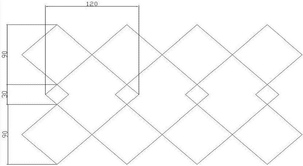
[0032] see image 3 and 5 , if the link size of the conveyor belt is added to the joint allowance, the range of the remainder generated by dividing by 90mm is: 15 Figure 5 The line marked as 2 is cut and looped to form image 3 Joint pattern shown: A small 30mm checkered pattern is obtained at the joint site.

[0033] After the cutting is completed, the following process steps are sequentially included: layering, punching, positioning, and hot pressing.

Embodiment 3

[0035] see Figure 4 and 5 , if the link size of the conveyor belt is added to the joint allowance, the range of the remainder generated by dividing by 90mm is: 45 Figure 5 The line marked 3 is cut and looped to form Figure 4 Joint pattern shown: A small 60mm checkered pattern is obtained at the joint site.

[0036] After the cutting is completed, the following process steps are sequentially included: layering, punching, positioning, and hot pressing.

[0037] The invention avoids the phenomenon that the pattern on the surface of the conveyor belt is interrupted at the joint; avoids the situation that the pattern on the surface of the conveyor belt is uneven at the joint; All convenient.


PUM


Abstract

The invention relates to a big grid pattern conveyer belt joint structure. The joint structure comprises the following three modes that (A) one end of a conveyer belt is cut along big grid diagonal lines, the conveyer belt link dimensions are added with the joint margin and then are divided by 90mm to obtain a remainder of being smaller than or equal to 15, and the other end of the conveyer belt is also cut along the big grid diagonal lines; (B) one end of the conveyer belt is cut along the big grid diagonal lines, the conveyer belt link dimensions are added with the joint margin and then aredivided by 90mm to obtain a remainder of being larger than 15 and smaller than or equal to 45, and the other end of the conveyer belt is cut along the position located 30mm behind the diagonal lines;and (C) one end of the conveyer belt is cut along the big grid diagonal lines, the conveyer belt link dimensions are added with the joint margin and then are divided by 90mm to obtain a remainder of being larger than 45 and smaller than or equal to 75, and the other end of the conveyer belt is cut along the position located 30mm in front of the diagonal lines. By means of the big grid pattern conveyer belt joint structure, the phenomena that patterns on the surface of the conveyer belt are broken at the joint positions and the patterns at the joints are rugged are avoided.

Description

technical field [0001] The invention relates to a joint structure and method of a conveyor belt with a large grid pattern, and belongs to the technical field of conveyor belt joints. Background technique [0002] The large square pattern of the conveyor belt generally refers to a pattern composed of square splicing with a side length of about 63mm and a diagonal length of about 90mm. It is widely used in the logistics industry to pick and transport and the luggage conveyor behind the airport check-in counter. [0003] As a common deep pattern (pattern depth: 4.0mm) in light-duty conveyor belts, the large square grid is often unable to connect the pattern at the joint due to the limitation of the final size during the looping operation. [0004] When the joints cannot be perfectly aligned, the existing technology usually adopts the following two methods: [0005] 1) Remove all the pattern at the joint and treat it as a flat belt, which is equivalent to the pattern on the su...

Claims


Application Information

Patent Timeline
Patent Type & Authority Applications(China)
IPC IPC(8): B65G15/32F16G3/10
CPCB65G15/32F16G3/10
Inventor 黄剑
Owner SHANGHAI YONGLI BELTING
Why Eureka
Eureka Blog
Learn More