Fan control method and device

A control method and fan technology, applied in the direction of engine control, pump control, mechanical equipment, etc., can solve problems such as no effective solutions are proposed

Inactive Publication Date: 2018-05-08
GREE ELECTRIC APPLIANCES INC
View PDF9 Cites 5 Cited by
  • Summary
  • Abstract
  • Description
  • Claims
  • Application Information

AI Technical Summary

Problems solved by technology

[0005] For how to reduce the noise generated by the

Method used


Image

  • Fan control method and device
  • Fan control method and device
  • Fan control method and device

Examples


Embodiment Construction

[0042] In order to make the object, technical solution and advantages of the present invention clearer, the present invention will be described in further detail below in conjunction with the embodiments and accompanying drawings. Here, the exemplary embodiments and descriptions of the present invention are used to explain the present invention, but not to limit the present invention.

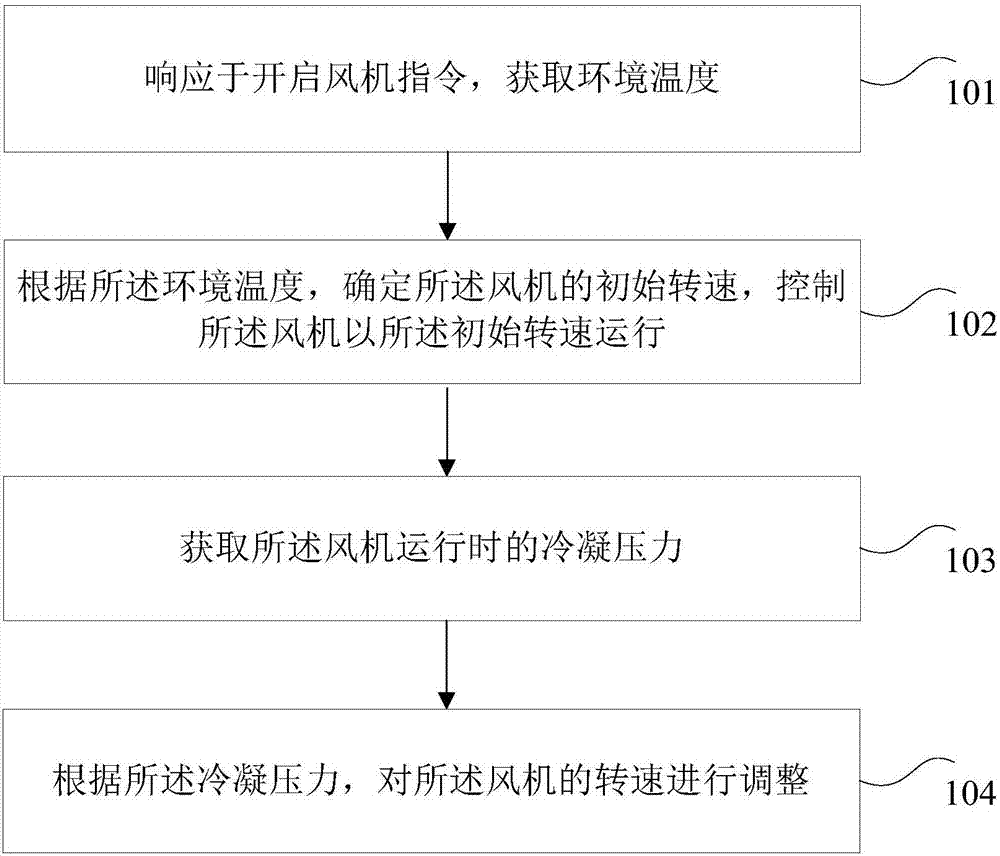
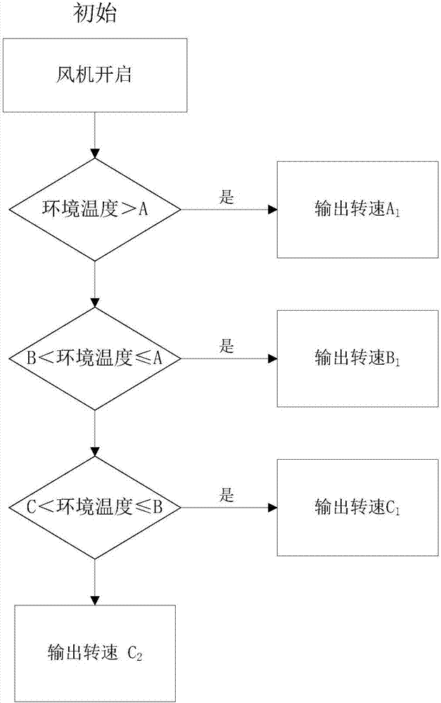
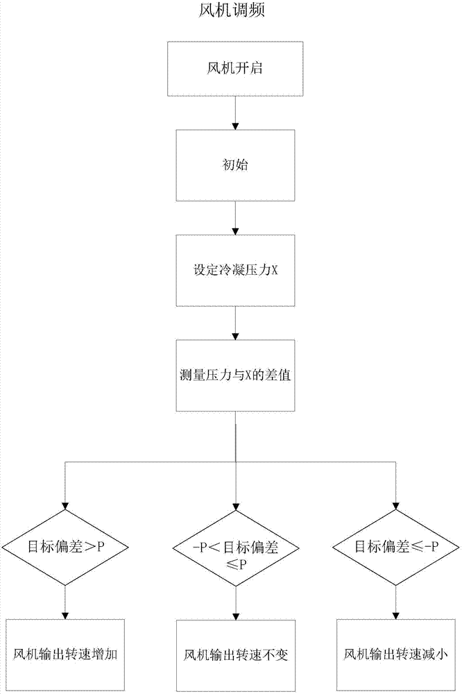
[0043] Considering that the fan will generate a lot of noise when it is running at full load, a fan control method is provided in this example, so that the fan can reduce the speed and reduce the noise while running. Considering the characteristics of the condensing pressure when the cooler is running and the commonly used ambient temperature, a reasonable condensing pressure can be set so that under the common ambient temperature, the condensing pressure of the cooler is always maintained near the preset value (for example: X). At a lower ambient temperature, the fan operates at a lower speed,...


PUM


Abstract

The invention provides a fan control method and device. The method comprises the steps of responding to a fan starting command, so that the environmental temperature is obtained; determining the initial rotating speed of a fan according to the environmental temperature, and controlling the fan to run at the initial rotating speed; obtaining the condensing pressure formed when the fan runs; and adjusting the rotating speed of the fan according to the condensing pressure. By means of the fan control method and device, the problem that existing fans run at the highest rotating speed all the time,so that noise is excessively large is solved; and the technical effect that the noise is effectively reduced is achieved.

Description

technical field [0001] The present invention relates to the technical field of equipment control, in particular to a fan control method and device. Background technique [0002] At present, in the manufacturing industry, machine tools are indispensable equipment. Among them, the existing machine tools only need to include: CNC, grinding machines, wire cutting machine tools, etc. In the process of machine tool operation, the high-speed operation of the cutting tool and the spindle will generate a lot of heat, which will cause thermal deformation of the guide rail and the spindle of the machine tool, which will inevitably reduce the machining accuracy of the workpiece, and will also reduce the cutting tool. Spindle life. Therefore, there is a demand for oil coolers, which can also be called oil coolers or coolers. [0003] However, due to modern technology and the improvement of user requirements for products, the cooling machine has relatively strict requirements on the noi...

Claims


Application Information

Patent Timeline
IPC IPC(8): F04D27/00
CPCF04D27/004F05D2260/96F05D2270/301F05D2270/303
Inventor 郭诗迪董扣胡乾龙石伟张丹丹
Owner GREE ELECTRIC APPLIANCES INC
Why Eureka
Try Eureka