Safe explosion venting device

An explosion venting and safety technology, applied in the field of explosion venting, can solve the problems of secondary explosion, loss, casualty and property, etc., and achieve the effect of avoiding secondary explosion, improving safety and high reliability

Pending Publication Date: 2018-05-08
张跃
View PDF13 Cites 0 Cited by
  • Summary
  • Abstract
  • Description
  • Claims
  • Application Information

AI Technical Summary

Problems solved by technology

[0003] Existing explosion venting devices are generally provided with an explosion vent door on the cavity. Once the gas explodes and generates a higher pressure, the explosion vent door will be pushed open to reduce the pressure in the cavity. It will enter the air, so that the residual combustible gas will cause a secondary explosion after contacting the air, and the secondary explosion will produce greater power, resulting in casualties and property losses

Method used


Image

  • Safe explosion venting device
  • Safe explosion venting device

Examples


Embodiment 1

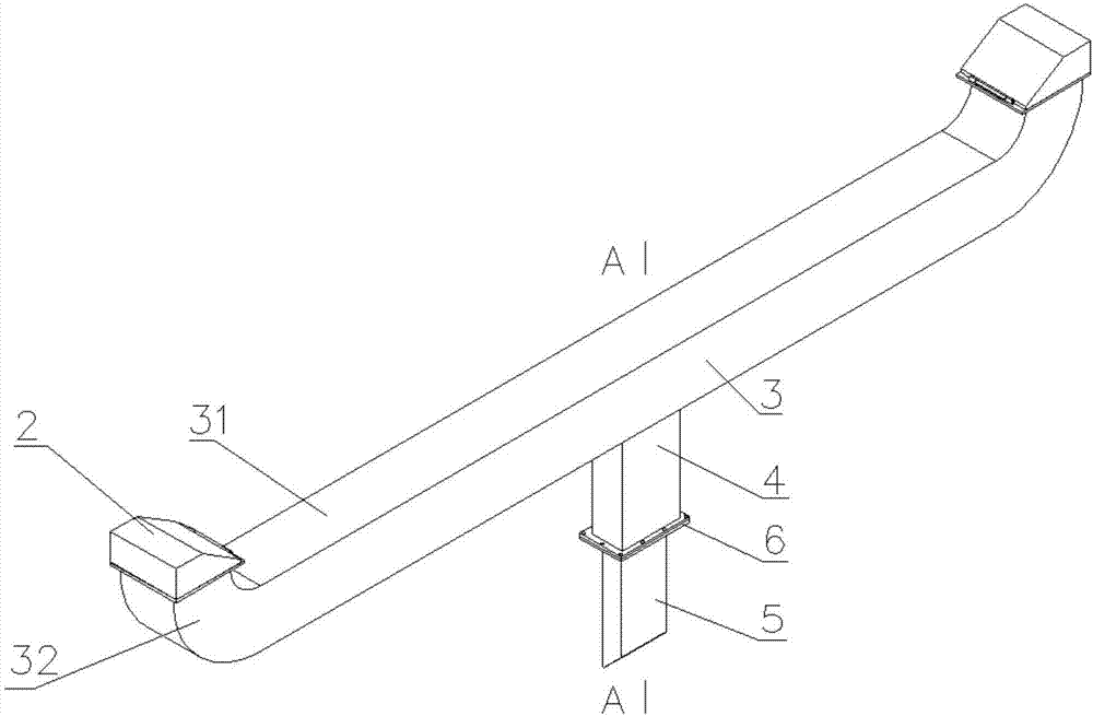
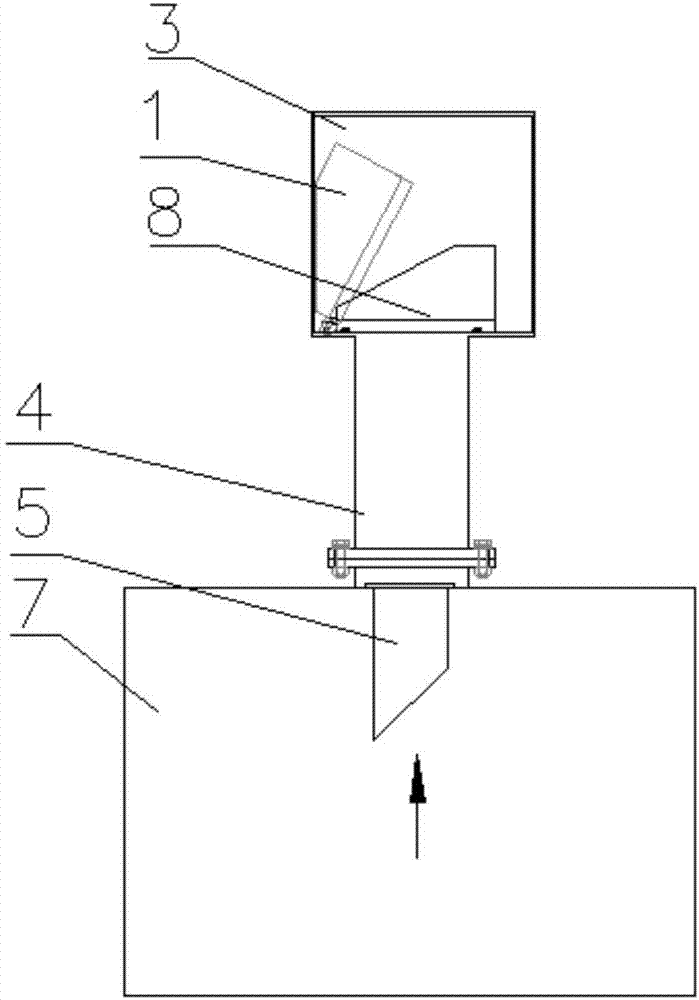
[0023] Such as figure 1 and figure 2 Shown: a safety explosion venting device, including a primary blast vent door 1 and a secondary blast vent door 2, an isolation cavity 3 is provided between the primary blast vent door 1 and the secondary blast vent door 2, and the isolation cavity 3 Filled with nitrogen.

[0024] The lower end of the primary explosion venting door 1 is fixedly connected with a hollow cavity 4, the lower end of the hollow cavity 4 is fixedly connected with the gas pipeline 5 through the flange 6, the lower end of the gas pipeline 5 extends into the working chamber 7, and the gas pipeline 5 is used to deliver nitrogen gas to the isolation chamber 3. The first-stage explosion venting door 1 is set in the isolation chamber 3, the upper end of the hollow cavity 4 is provided with a connecting seat 8, one end of the first-stage explosion venting door 1 is hinged with the connecting seat 8, and the other end is provided with a counterweight, which is connected...

Embodiment 2

[0029] The difference from Embodiment 1 is that the isolation cavity is filled with carbon dioxide.

[0030] Others are with embodiment 1.

Embodiment 3

[0032] The difference from Embodiment 1 is that there is one secondary explosion vent door, and the secondary explosion vent door is connected to the arc-shaped corner at one end of the isolation chamber. The other end of the isolation cavity may directly close one end of the cuboid without setting an arc-shaped corner; it may also be provided with a closed arc-shaped corner.

[0033] In this embodiment, the counterweight of the secondary explosion venting door may be greater than that of the secondary explosion venting door in Embodiment 1.

[0034] Other structures are with embodiment 1.

[0035] Since this embodiment can be understood by those skilled in the art, it is not shown in the drawings again.


PUM


Abstract

The invention discloses a safe explosion venting device. The explosion venting device comprises a primary explosion venting door and a secondary explosion venting door, wherein an isolation cavity isformed between the primary explosion venting door and the secondary explosion venting door, and non-flammable and combustible gas is filled in the isolation cavity. According to the explosion ventingdevice, the gas subjected to primary explosion venting is prevented from being in contact with air, so that secondary explosion is avoided, damage to the surrounding environment is avoided, and the safety is greatly improved.

Description

technical field [0001] The invention relates to the technical field of explosion venting, in particular to a safety explosion venting device. Background technique [0002] Due to the confinement, the gas explosion will produce high pressure and pressure rise rate, so as to cause casualties and property damage. Combustible substances (combustible gas, steam and dust) and air (or oxygen) must be uniformly mixed within a certain concentration range to form a premixed gas, which will explode when it encounters a fire source. This concentration range is called the explosion limit, or explosion limit. Concentration limit, it can be used to assess the size of the explosion hazard of combustible gas. [0003] Existing explosion venting devices are generally provided with an explosion vent door on the cavity. Once the gas explodes and generates a higher pressure, the explosion vent door will be pushed open to reduce the pressure in the cavity. It will enter the air, so that the res...

Claims


Application Information

Patent Timeline
Patent Type & Authority Applications(China)
IPC IPC(8): F16K17/12F16K17/164
CPCF16K17/12F16K17/164
Inventor 张跃
Owner 张跃
Why Eureka
Try Eureka