Fingerprint module group identification code scanning device and scanning method

A fingerprint module and scanning device technology, applied in the direction of measuring devices, instruments, measuring electronics, etc., can solve the problems of low efficiency of identification codes, unfavorable organizations for automatic testing of fingerprint modules, and reduced testing efficiency of fingerprint modules, so as to achieve accurate lifting Stable, simple and practical structure

Active Publication Date: 2018-05-08
HANGZHOU CHANGCHUAN TECH CO LTD
View PDF9 Cites 4 Cited by
  • Summary
  • Abstract
  • Description
  • Claims
  • Application Information

AI Technical Summary

Problems solved by technology

[0003] The purpose of the present invention is to overcome the current manual recording of the identification code on the fingerprint module and corresponding to the measured data. The efficiency of recording the identification code on the fingerprint module is low, which reduces the testing efficiency of the fingerprint module and is not conducive to the organization of fingerprints. Insufficiency of module automation testing provides a fingerprint module identification code scanning device and scanning method with high efficiency for recording the identification code on the fingerprint module, improving the testing efficiency of the fingerprint module and facilitating the organization of automatic testing of the fingerprint module

Method used


Image

  • Fingerprint module group identification code scanning device and scanning method
  • Fingerprint module group identification code scanning device and scanning method
  • Fingerprint module group identification code scanning device and scanning method

Examples


Embodiment Construction

[0019] The present invention will be further described below in conjunction with the accompanying drawings.

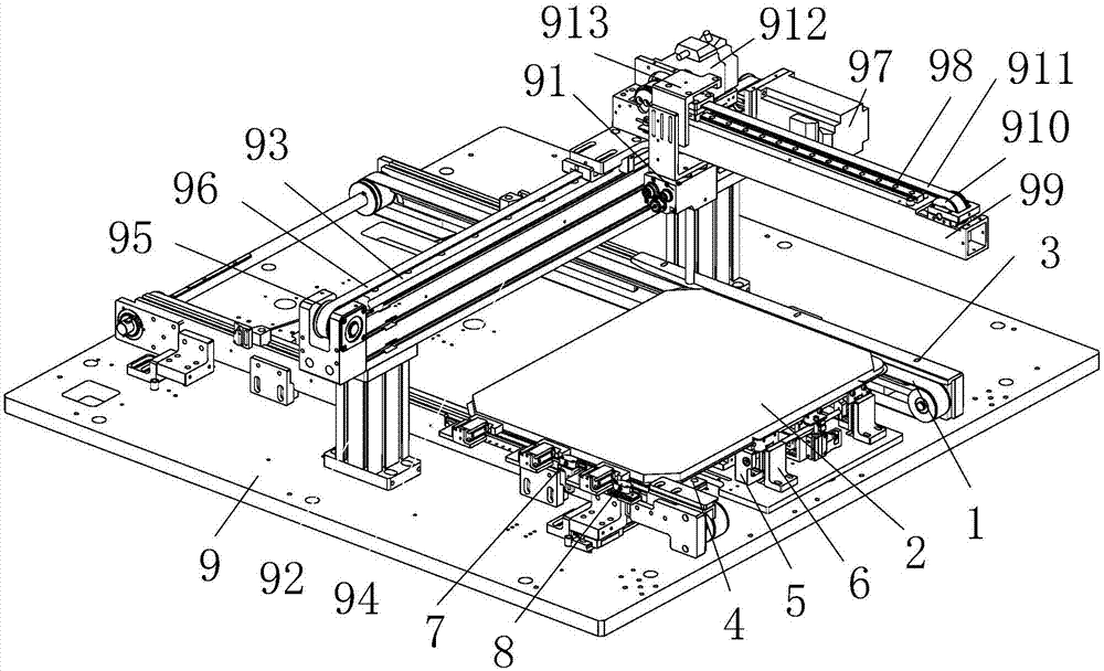
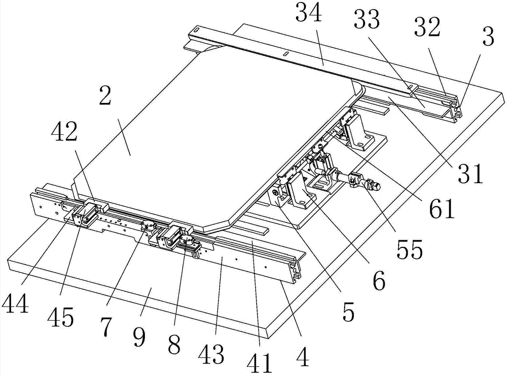
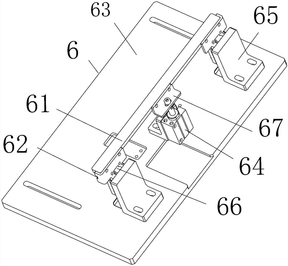
[0020] as attached figure 1 , attached figure 2 , attached image 3, attached Figure 4 Shown:

[0021] A fingerprint module identification code scanning device, comprising: a bottom plate 10, two conveyor belts 1, a material tray 2 placed on the conveyor belt 1 for transportation, a material tray positioning device, and a code scanning device located above the material tray positioning device The scanning manipulator 9 of 91; the tray positioning device includes: a fixed rib 3 arranged on the outside of one conveyor belt 1 and provided with a side accommodating groove 31 matching with the side end clearance of the tray 2, and located on the other conveyor belt 1 The outer side is provided with a support plate 41 positioned at the lower side of the tray 2 and a side jacking mechanism 4 of two side jacking blocks 42, and a positioning and pressing mechanism 5 betwe...


PUM


Abstract

The objective of the invention is to provide a fingerprint module group identification code scanning device and scanning method. The fingerprint module group identification code scanning device comprises a baseplate, two conveying belts, a material tray, a material tray positioning device and the scanning manipulator of a code scanning device arranged above the material tray positioning device. The material tray positioning device comprises a fixed stop side which is arranged on the external side of one conveying belt and provided with a side accommodating groove matched with the material trayside end, a side ejecting mechanism which is arranged on the external side of the other conveying belt and provided with a supporting plate arranged on the lower side of the material tray and at least one side ejecting block, an inlet positioning and compressing mechanism which is arranged between the fixed stop side and the side ejecting mechanism and an elevating end stop mechanism which is provided with an end stop strip, an inlet detection sensor and a positioning detection sensor, wherein the rear end of the end stop strip is provided with an end accommodating groove matched with the endside of the material tray. According to the fingerprint module group identification code scanning device, the efficiency of recording the identification code on the fingerprint module group is high so that the fingerprint module group test efficiency can be enhanced and organizing the fingerprint module group automatic test can be facilitated.

Description

technical field [0001] The invention relates to the field of fingerprint module testing, in particular to a fingerprint module identification code scanning device and a scanning method. Background technique [0002] Communication equipment is updated with each passing day, information security is becoming more and more important, and fingerprint recognition technology has become more and more mature with the development of communication equipment; the invention of Chinese patent application number: CN201610878055.1 discloses a fingerprint module testing machine, It includes a body on which a fingerprint testing device and a delivery device for transporting fingerprint modules are arranged; the fingerprint testing device includes a horizontal moving device, a vertical moving device and a simulated fingerprint device, and the simulated fingerprint device is arranged on the vertical On the moving device, the vertical moving device is arranged on the horizontal moving device. Wh...

Claims


Application Information

Patent Timeline
Patent Type & Authority Applications(China)
IPC IPC(8): G01R31/01
CPCG01R31/01
Inventor 谢周阳翁水才
Owner HANGZHOU CHANGCHUAN TECH CO LTD
Why Eureka
Try Eureka