
Multifunctional household shoe drying and deodorizing device

A drying device and multi-functional technology, applied in the field of shoes, can solve the problem of single deodorizing equipment and cannot simultaneously dry, deodorize, and disinfect, achieve simple and reasonable structural design, save home space, and avoid multiple sets The effect of machine settings

Inactive Publication Date: 2018-05-11
珠海横琴华发七弦琴知识产权服务有限公司
View PDF10 Cites 1 Cited by
  • Summary
  • Abstract
  • Description
  • Claims
  • Application Information

AI Technical Summary

Problems solved by technology

[0005] The purpose of the present invention is to provide a new multi-functional household shoes drying and deodorizing machine, through the design of the first chamber and the second chamber to solve the problem that the shoe drying equipment or deodorizing equipment in the prior art is single and cannot be used at the same time. Technical issues related to the integration of drying, deodorization and disinfection

Method used


Image

  • Multifunctional household shoe drying and deodorizing device
  • Multifunctional household shoe drying and deodorizing device
  • Multifunctional household shoe drying and deodorizing device

Examples


Embodiment 1

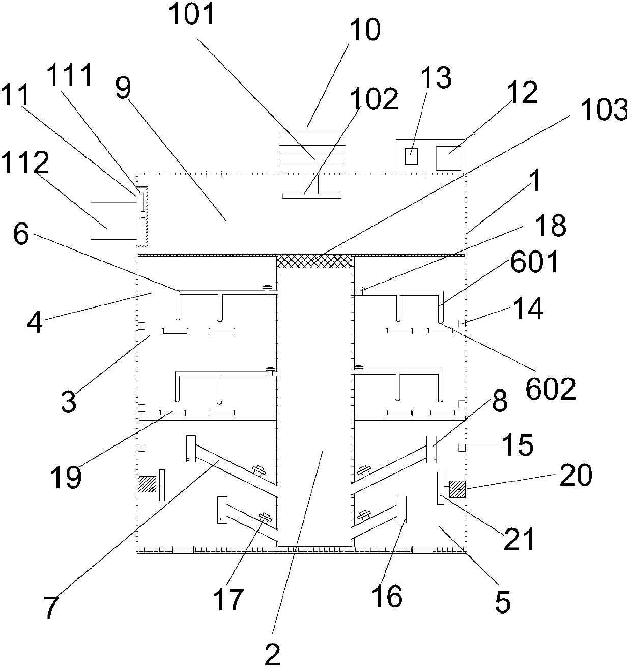
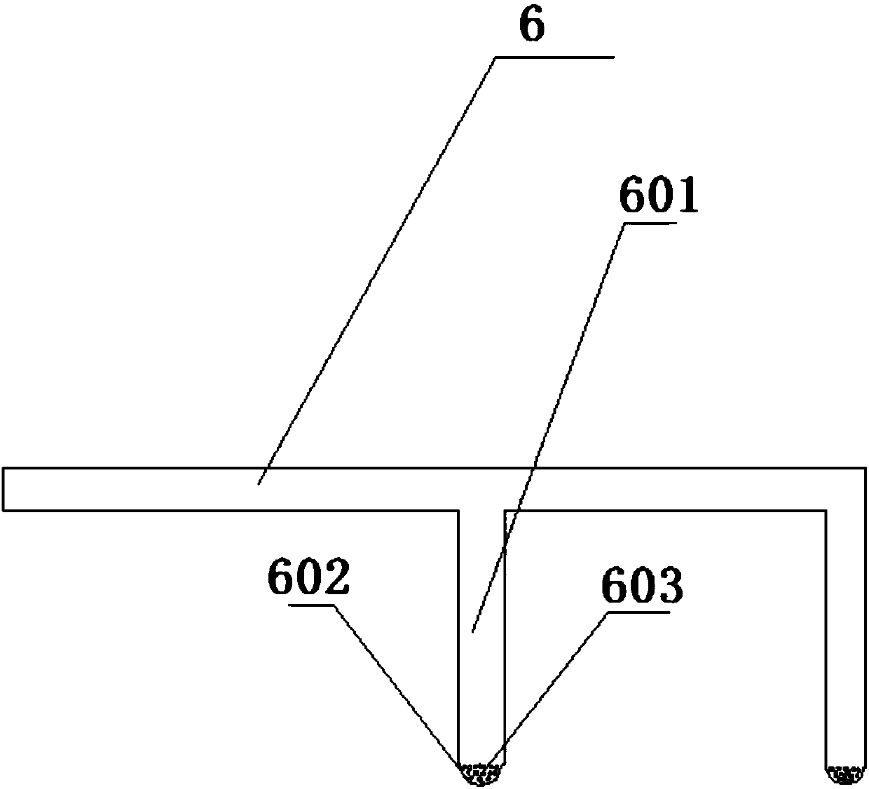
[0031] Such as figure 1 As shown, a multifunctional household shoes drying and deodorizing device includes a box body 1, and an air duct 2 is arranged in the box body, and the air duct divides the box body into left and right chambers. The chamber is provided with a multi-layer partition 3, which divides the chamber into a first chamber 4 for shoe sterilization and a second chamber 5 for drying shoes, and the second chamber is placed At the lower end of the first chamber, a first air outlet pipe 6 corresponding to the first chamber and a second air outlet pipe 7 corresponding to the second chamber are provided on the side wall of the air duct. The first air outlet pipe and the second air outlet pipe communicate with the air duct, and the free end of the second air outlet pipe is provided with a shoe support frame 8; the top of the box is also provided with a draft tube 9, The air-inducing tube is a T-shaped structure, and the air-inducing tube penetrates from the top of the b...

Embodiment 2

[0051] The shoe cleaning machine in the present invention is an improvement on the basis of the first embodiment. The technical content disclosed in the first embodiment will not be described repeatedly, and the content disclosed in the first embodiment also belongs to the content disclosed in this embodiment.

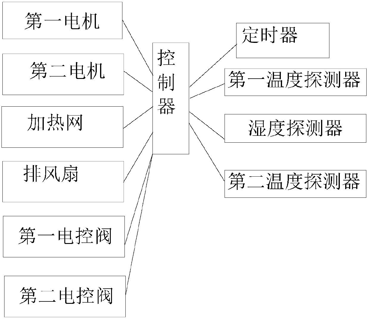
[0052] In the present invention, an ultraviolet lamp is also installed in the first chamber; the ultraviolet lamp, the timer and the controller are electrically connected to realize the sterilization and disinfection of shoes through the ultraviolet lamp

[0053] The light ultraviolet lamp is an existing device, so it is not shown in the figure, and its specific structure will not be repeated here.


PUM


Abstract

The invention relates to the technical field of shoes, in particular to a multifunctional household shoe drying and deodorizing device; the device comprises a cabinet body, an air duct is arranged inthe cabinet body, the cabinet body is divided into left and right chambers by the air duct, multiple layers of separation plates are arranged in the chambers, the chambers are divided into first chambers used for conducting sterilization on the shoes and second chambers used for conducting drying on the shoes, the second chambers are arranged below the first chambers, first air outlet pipes corresponding to the first chambers and second air outlet pipes corresponding to the second chambers are arranged on the side walls of the air duct, and the first air outlet pipes and the second air outletpipes are communicated with the air duct. The invention aims at achieving the purpose of providing the novel multifunctional household shoe drying and deodorizing device, and the technical problem that integration of drying, deodorizing and sterilizing cannot be simultaneously achieved due to the fact that existing shoe drying equipment or deodorizing equipment in the prior art has a single function is solved.

Description

technical field [0001] The invention relates to the technical field of shoes, in particular to a multifunctional household shoe drying and deodorizing device. Background technique [0002] With the improvement of the quality of life, people have higher and higher requirements for the quality of life. They also put forward higher requirements for the comfort of the shoes that must be worn every day. Many people wear shoes for a day, and the shoes will be more If it is wet, you will feel uncomfortable if you wear it the next day, and if the shoes are in a wet state for a long time, not only the inside of the shoes will produce odor, but also it is easy to breed bacteria, which will bring unnecessary troubles to people's lives. [0003] Then there is the rainy day, the shoes are often wet, and people usually clean the shoes that can be scrubbed, but it often takes one to two days to dry, which delays the next day’s travel, or replaces the shoes, and for the shoes that cannot be...

Claims


Application Information

Patent Timeline
IPC IPC(8): A47L23/20A61L2/10A61L2/24A61L9/16
CPCA47L23/205A61L2/10A61L2/24A61L9/16A61L2202/14A61L2209/11
Inventor 夏德兴王欣洁
Owner 珠海横琴华发七弦琴知识产权服务有限公司
Features
  • Generate Ideas
  • Intellectual Property
  • Life Sciences
  • Materials
  • Tech Scout
  • Unparalleled Data Quality
  • Higher Quality Content
  • 60% Fewer Hallucinations
Learn More