an endoscopic device

An endoscope and object technology, applied in the field of endoscopy, can solve the problems of image overexposure, inability to observe the treatment spot irradiation area, monitor the PDT treatment process, etc., to achieve the effect of ensuring visualization and clinical effect

Active Publication Date: 2020-12-18
SONOSCAPE MEDICAL CORP
View PDF6 Cites 0 Cited by
  • Summary
  • Abstract
  • Description
  • Claims
  • Application Information

AI Technical Summary

Problems solved by technology

[0005] The therapeutic optical power of PDT can usually reach 1-2W, and the optical power density can usually reach 0.1W / cm when irradiating the lesion area at close range. 2 ~1W / cm 2 Therefore, when PDT cooperates with the endoscope to implement intracavitary tumor treatment, there is often the following problem, that is, the intensity of the therapeutic light received by the image sensor and reflected by the subject far exceeds the linear response range of the image sensor, resulting in The image is overexposed, resulting in the inability to use the endoscope to monitor the adverse effects of the PDT treatment process in real time
[0006] In order to eliminate the image overexposure problem caused by the treatment light, someone in the prior art proposes to install a light cut filter between the subject and the endoscope imaging unit, and the treatment light can be cut off by the light cut filter. That is, in the reflected light reflected by the subject, the intensity of the therapeutic light entering the image sensor of the imaging part is 0. Although the problem of image overexposure can be eliminated in this way, people cannot pass the light reflected by the subject. The reflected light image is used to observe the irradiated area of ​​the treatment spot, which may lead to the problem that the PDT treatment is difficult to achieve the expected effect because the PDT treatment spot does not completely cover the lesion area

Method used


Image

  • an endoscopic device
  • an endoscopic device
  • an endoscopic device

Examples


Embodiment Construction

[0048] The following will clearly and completely describe the technical solutions in the embodiments of the present invention with reference to the accompanying drawings in the embodiments of the present invention. Obviously, the described embodiments are only some, not all, embodiments of the present invention. Based on the embodiments of the present invention, all other embodiments obtained by persons of ordinary skill in the art without making creative efforts belong to the protection scope of the present invention.

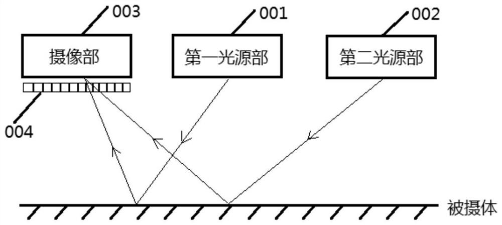
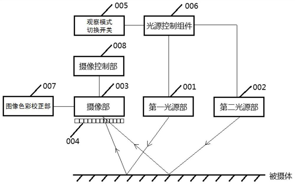
[0049] The embodiment of the present invention discloses an endoscope device, seefigure 1 shown, including:

[0050] a first light source unit 001 for projecting illumination light to the subject;

[0051] a second light source unit 002 for projecting therapeutic light to the subject;

[0052] an imaging unit 003 for taking an image of the subject by using light reflected from the subject;

[0053] A light cut-off filter 004 is arranged between the subject a...


PUM


Abstract

The present application discloses an endoscope device, comprising: a first light source unit for projecting illumination light to a subject; a second light source unit for projecting therapeutic light to the subject; An imaging unit that captures images of the subject; it is arranged between the subject and the imaging unit, and has a light cut-off whose transmittance to therapeutic light is greater than zero and less than the upper limit threshold of the transmittance determined in advance based on the principle of avoiding image overexposure filter. On the one hand, this application can avoid the image overexposure problem caused by the treatment light, and ensure the visualization of the photodynamic therapy process; The received image contains the spot irradiation area of ​​the treatment light, which helps the medical staff to adjust the spot size and position of the treatment light in time according to the spot irradiation area of ​​the treatment light, so that it can accurately cover the lesion area of ​​the subject, ensuring Clinical effects of photodynamic therapy.

Description

technical field [0001] The invention relates to the technical field of endoscopes, in particular to an endoscope device. Background technique [0002] Photodynamic therapy (Photodynamic Therapy, PDT) has been proven to be an effective means of treating malignant tumors and precancerous lesions. The clinical operation of PDT includes the following two main steps: (1) Intravenous injection of photosensitizer into the patient, after several hours or dozens of hours of metabolism in the human body, it will be enriched in the lesion tissue; (2) According to photosensitizer The specific wavelength band and corresponding dose of therapeutic light are irradiated to the lesion tissue. [0003] The principle of PDT to treat tumors is as follows: After the photosensitizer molecules enriched in the lesion absorb photons, the energy state changes from a steady state to a high-energy state, and the energy is transferred to the oxygen molecules (triple oxygen 3O2) in the biological tissue...

Claims


Application Information

Patent Timeline
Patent Type & Authority Patents(China)
IPC IPC(8): A61N5/06A61N5/067A61B1/04A61B1/06
CPCA61N5/06A61B1/04A61B1/06A61N2005/0663A61N2005/0667A61N2005/0658A61N2005/0643A61N2005/063A61N2005/0626A61N5/067A61B1/0638A61B1/0646A61B1/0684A61B1/00186A61B1/05A61B1/063A61N2005/0662A61N2005/0651A61N5/0601A61N5/062A61B1/000095A61B1/0655A61B1/0661A61B1/00006A61B1/00087
Inventor 邱建军陈云亮冯能云董二伟
Owner SONOSCAPE MEDICAL CORP
Why Eureka
Try Eureka