Building shock absorbing device
A shock-absorbing device and building technology, applied in the direction of buildings, building components, building types, etc., can solve the problems of poor seismic capacity, economic losses, personnel damage and other problems of building prefabricated houses, achieve good shock absorption effect, improve structural performance, fix solid effect
- Summary
- Abstract
- Description
- Claims
- Application Information
AI Technical Summary
Problems solved by technology
Method used
Image

Examples
Embodiment Construction
[0015] The following will clearly and completely describe the technical solutions in the embodiments of the present invention with reference to the accompanying drawings in the embodiments of the present invention. Obviously, the described embodiments are only some, not all, embodiments of the present invention. Based on the embodiments of the present invention, all other embodiments obtained by persons of ordinary skill in the art without making creative efforts belong to the protection scope of the present invention.
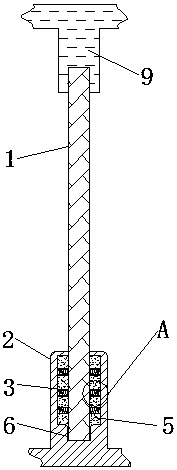
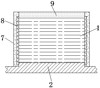
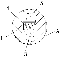
[0016] see Figure 1-4 , the present invention provides a technical solution: a building shock absorbing device, including a building wall 1, a shock absorbing tank body 2, a shock absorbing ring column 3, a shock absorbing spring 4, a concrete layer 5, a fixing groove 6, and a shock absorbing column 7. Card slot 8, fixed tank body 9 and elastic cotton board 10, the bottom of building wall 1 is fixedly connected with shock-absorbing tank body 2, and shock-abso...
PUM
 Abstract
Description
Claims
Application Information